Investigate how the length of wire effects its resistance.
SC1: HARD TO RESIST
Theory
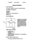
What is resistance?
Electricity is conducted through a conductor, in this case wire, by means of free electrons. The number of free electrons depends on the material and more free electrons means a better conductor, i.e. it has less resistance. For example, gold has more free electrons than iron and, as a result, it is a better conductor. The free electrons are given energy and as a result move and collide with neighbouring free electrons. This happens across the length of the wire and thus electricity is conducted. Resistance is the result of energy loss as heat. It involves collisions between the free electrons and the fixed particles of the metal, other free electrons and impurities. These collisions convert some of the energy that the free electrons are carrying into heat.
How is it measured?
The resistance of a length of wire is calculated by measuring the current present in the circuit (in series) and the voltage across the wire (in parallel). These measurements are then applied to this formula:
V = I ´ R where V = Voltage, I = Current and R = Resistance
This can be rearranged to:
R = V/ I
Ohm's Law
It is also relevant to know of Ohm's Law, which states that the current through a metallic conductor (e.g. wire) at a constant temperature is proportional to the potential difference (voltage). Therefore V ¸ I is constant. This means that the resistance of a metallic conductor is constant providing that the temperature also remains constant. Furthermore, the resistance of a metal increases as its temperature increases. This is because at higher temperatures, the particles of the conductor are moving around more quickly, thus increasing the likelihood of collisions with the free electrons.
Task:
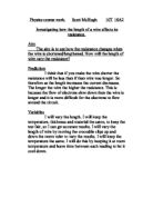
Our aim is to investigate how the length of wire effects its resistance
In this investigation I will be looking at the resistance of wires to an electrical current and determining the factors that affect the resistance of a wire.
There are five main factors that affect the resistance of a piece of wire. These are as follows:
) The material that the wire is made of.
2) The length of the wire
3) The thickness (or diameter) of the wire.
4) The temperature of the wire.
5) Voltage of the circuit.
However, in my investigation I will only be looking at two different factors that affect the resistance of the wire. These two factors are length of the wire and thickness of the wire.
Input variables of this investigation I could study are:
Length of wire
2 Material of wire
3 Thickness of wire
The input variable I have chosen to investigate is length of the piece of wire.
The variables I need to keep the same are:
Thickness of wire
2 Material of wire
Also, I must use the same equipment to take every reading. This is because equipment such as voltmeters and multimeters can sometimes give slightly different results from other appliances of the same kind.
The outcome variable I am going to measure is the resistance of the wire. To calculate the resistance of the wire, I will need to take two measurement from the experiment. These are Voltage (V) and Current (A). The resistance can be calculated using Ohm's law; R = V/I
I will be using a variable resistor to decrease or increase the amount of current flowing through the circuit.
This maybe useful when the current is low to get an accurate reading of the voltmeter and Multimeter, and also if the current is too high. It should not affect my results as both voltage and current will change in the same ratio, so my resistance calculation remains unaffected.
Prediction
What I think will happen is that as the length of the piece of wire increases, the resistance will also increase in a directly proportional manner. ...
This is a preview of the whole essay
I will be using a variable resistor to decrease or increase the amount of current flowing through the circuit.
This maybe useful when the current is low to get an accurate reading of the voltmeter and Multimeter, and also if the current is too high. It should not affect my results as both voltage and current will change in the same ratio, so my resistance calculation remains unaffected.
Prediction
What I think will happen is that as the length of the piece of wire increases, the resistance will also increase in a directly proportional manner. I predict that The longer the wire, the higher the resistance.
This is because the longer the wire, the more times the free electrons will collide with other free electrons, the particles making up the metal, and any impurities in the metal. Therefore, more energy is going to be lost in these collisions (as heat).
Furthermore, doubling the length of the wire will result in double the resistance. This is because by doubling the length of the wire one is also doubling the collisions that will occur, thus doubling the amount of energy lost in these collisions.
I think this will happen because of the principle of Ohm's Law, which sates that:
The resistance will increase as more atoms hamper the electrons progress through the wire as it gets longer, and so more voltage is needed for the electrons to move. This will result in less current and more voltage, so therefore more resistance.
To explain this idea, I will start by explaining the concept of electron flow. Conventional current flow is right to left. On diagrams of circuits, we show current as going from right to left, from the positive end of a cell to the negative end. However, in reality, the electrons that make up the current actually travel the other way i.e. from the negative to the positive or from left to right. This doesn't really make any difference to the experiment, but the behaviour of the electrons as they pass through the wire does make a difference.
Using this model of resistance arising from collisions between electrons and lattice ions means that I can predict that:- Resistance is directly proportional to length because doubling the length would double the chance of a collision.
Information obtained from: www.skool.co.uk
I predict my graph to look like the following:
Apparatus
Power Pack (To supply power)
Wires (x6) (To allow current to flow through the circuit)
Voltmeter (To measure voltage)
Bare wire (I will change the length of this for my input variable)
Wire Cutters (To cut the wire)
Rheostat (Variable Resistor, to increase or decrease current if needed)
Sellotape (To secure wire to table)
Crocodile Clips (To connect normal wires with the bare wire)
Metre Ruler (To measure the length of the bare wire)
Method
In this investigation I will do as follows:
As I will be investigating one variable at a time, I will need to keep the other variables constant. When measuring the length I will always use the same material: Contra wire. Also I will make sure that the wire does not get hot by not measuring any less than 10cm. Also, I will always use the same thickness wire.
However, when I am looking at the factor of thickness I will make sure that the wire does not get hot, that the wire is Contra wire.
I need to keep the variables that I am not looking at or measuring the same at all times because of the fact that if I have two variables varying at the same time then I will not
know which variable affected my results or how much it affected them. Because of this I will only be looking at one factor at a time to make sure that my results are as accurate and true as possible. In both factors I will always be using the same voltage throughout.
I will look at the factor of length first. In this I will keep the variables that I am not investigating the same so as to make it a fair test. Then, I will set up my circuit without a variable resistor. If the power supply alone does not give me enough control over the voltage to get it at the optimum voltage for this investigation I will use a rheostat to give more precise control. (See next two pages for circuit diagrams.) Then, I will take readings of the voltage and current from the voltmeter and ammeter when the wire is 10cm.
In simple terms I will be taking the following steps in to consideration:
Plan of action:
) Collect the equipment as shown above.
2) Set up equipment, as shown below.
3) Attach the wire to the metre ruler with Sellotape, a piece at each end of the ruler with the wire stretched taut.
4) Use the crocodile clips to complete the circuit; attach one crocodile clip, permanently to the '0 cm' mark.
5) Measure out the lengths of wire (30,40,50,60,70,80,90 and 100 cm) by moving the second crocodile clip up the wire and metre ruler, to the points specified.
6) Note down the voltage and the current from the ammeter and voltmeter
7) Calculate resistance using the equation R=V/I
8) Repeat for a different voltage, which voltage doesn't matter as these experiments are done to test the Ohms Law idea (see Evaluation).
9) Place results on a graph where the axis Y = resistance (ohms) and axis X = Wire length (cm) and also average the results and draw the relevant line of best fit on the graph so that all the results are comparable.
0) Study the results.
The circuit will be set up as follows:
Obtaining Evidence
Safety precautions
In order to perform a safe experiment, a low voltage of 2V was chosen so that overheating was minimilised. Furthermore, lengths lower than 20cm were not tried, which also helped to avoid overheating.
All the connecting wires will be insulated to prevent shocks or short circuits. I will be using a low voltage so that the test wire does not get too hot and to lessen the possibility of damage from an electric shock.
I will not touch any electrical equipment with wet hands and I understand what to do in the event of someone receiving an electric shock. There is also a carbon dioxide fire extinguisher in the laboratory in case of an electrical fire.
Accuracy:
I will use a 2 volt power supply from a mains powered power pack. I will not be using a voltmeter in the preliminary work as it is only a mini practical to experiment with the apparatus and results.
I can achieve more accurate and useful results if I can keep the number of variables down to one. This way my analysis of my results will be clearer. For this same reason I will use only one thickness and kind of wire.
I will check that the ammeter and voltmeter that I use have their needles on zero before I integrate them into my circuit and I shall double check my circuit set up prior to starting my experiment.
I will first test my circuit with no test wire, and just touch the crocodile clips together so that I can subtract the resistance of the circuit's wire.
Preliminary work
I will carry out the above experiment for my preliminary work before I carry out the actual practical. This is to be certain that the method can be done easily and to check any anomalous results.
This is one of the most important parts of the investigation. A Preliminary experiment enables us
. To see whether the method tests the hypothesis in the most effective way possible i.e. if it is a good way to test the hypothesis and,
2. To test which are the best values to keep the constant variables at.
The preliminary experiment that will be attempted will be to find out the best value to keep the current at and to find the best length of wire to use. Various lengths and only a small range of results will be collected. Too small a wire and heating can occur. Similarly, too large a current will cause heating and too small will cause a small range to be collected. A compromise is needed. It will also decide the best material to use. Ideally, one with the largest resistance should be used as this will give the largest range. Again, as with the other constant variables, too high a resistance will cause heating.
Diagram:
The following results table indicates the results that we achieved when calculating the amount of resistance at different lengths of the contra wire.
Results table
From using the results gained from the preliminary work, I have worked that we will do this experiment at 2V as in the preliminary work this showed a more definite and almost equal increase in resistance each time the length was increased.
After performing these rough trials, it was decided that 2V would be used in the proper experiment, as it provided results from 30cm up to 100cm and the higher voltage provided no additional ease of measurement.
Furthermore, it was also decided to allow the wire to cool between experiments as considerable heat was noticed at lower lengths and, as mentioned above, an increase in temperature results in an increase in resistance. By allowing the wire to cool between experiments a fair test could be assured.
Analysis
Using scientific knowledge in my prediction, the graph has turned out like it should have and that my results are accurate. As the length of the contra wire increases, the voltage increases but the current decreases. Using the equation;
Resistance = Voltage / Current I have worked out the resistance, according to Ohm's Law.
The graph shows a directly proportional relation between the length of the wire and its resistance which is what I predicted earlier in the investigation.
I found out the gradient of the graph by constructing a right angled triangle whose hypotenuse is on the line. The gradient is then given by x /y which resulted to 0.033.
To support this value, this example of y = mx + c; 0.003 + 0.6 (this was found by taking the line further until it met the y axis. Therefore if look at the 30 cm length wire y = 0.033 * 30 + 0.6 =
From my graph, I have found the pattern that the longer the wire, the higher the resistance becomes. The graph shows that as the length of the wire increases, so does the resistance of the wire. An example of this is when the experiment at 30cm was taken place and the resistance was 1.12 ?. When 10 cm more was added on, the amount of resistance at 40cm was 1.45?. The reason for this occurring is because the current has had to pass through more atoms in the wire so there is an increase in resistance for the current.
Evaluation
To evaluate this investigation analytically I have learned a few things in this practical which determine the resistance of a wire. Firstly and possibly most importantly, is the length. the longer the wire the more obstruction the electrons of the current have when trying to travel through it. For example, electrons travelling along a really long wire will encounter more atoms of the wire to pass through than a really short one. So, the longer the wire will result to more resistance.
Secondly is the area of the wire. a larger wire cross-section will mean there is more room for the electrons to pass through, therefore there will be less resistance per electron. larger wire cross-section area means less resistance.
Thirdly is the material of the wire. A wire with more electrons on the outer shell of the atom means less resistance as more electrons can pass through. However, a denser material will have more atoms per the same amount of space in the wire. this means there will be more electron-atom collisions, which makes it harder for the electrons to pass through the wire, more resistance.
If the practical is to be repeated I would calculate the resistance of different lengths other than a 10 cm gap as I found the usual pattern 30cm 40cm etc was too small.
I would also do the experiment at 4 V as it would give a more definite result and more increase in resistance.
I did not have anomalous results this could have been due to a unique error in the measuring and /or reading of the meters, or a temperature change. These results could be done better by using a multimeter . If I were to do this experiment again, I would use newer, more accurate ammeters and voltmeters, a more accurate method of measurement, and take a much wider range of readings so that a more accurate average can be taken. I would also investigate other factors, such as temperature, voltage and current, and see how these effect the resistance. I would also do the experiments under different conditions such as temperature and pressure to see if it makes any difference to resistance.