Physics coursework yr10: Resistance of a wire
Planning
Aim: To investigate how the resistance of a wire changes
Key factors:
* Voltage across wire (higher the voltage, the faster electrons flow and the resistance does not change)
* Current in circuit (higher the current the more electrons going through the wire, so more resistance)
* Length of a wire (the longer the wire the more resistance)
* Thickness of wire (the more thicker the wire the less the resistance there is)
* Light dependant resistor (light intensity decreases the resistance increases)
* Temperature (If temperature gets too high then wire could melt and if temperature gets too low then wire could snap).
Prediction:
I predict that the longer the wire, the higher the resistance. This is because if the wire is short the electrons will flow straight through and not bump/collide into each other, but if you increase the wire length the electrons have to travel further and this means that they will collide more into each other, creating more resistance. Also the more current there is, the more resistance there is, because the more electrons there are in the wire the more they will collide into each other. If you increase voltage the electrons flow faster and not collide as much. This means that the resistance will decrease. Also the more voltage there is, the resistance decreases because the electrons are pushed faster. My graph should show length is directly proportional to the resistance. E.g. if the wire is 50cm long there should be half the number of collisions between electrons and atoms, but if the wire is twice as long as 50cm (100cm) then there is twice the number of atoms and this would mean twice as many collisions and therefore twice the resistance. I will plot a length vs. resistance graph to show this.
.
Apparatus:
* 100cm ruler: To hold wire in place and measure wire.
* Ammeter and Voltmeter: To take readings
* Power pack: To supply current and voltage
* Sellotape: Rap around ruler and wire to hold the wire in place securely
* Crocodile clips: To attach the wire to the ruler and power pack
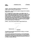
Diagram of circuit:
Method:
. Attach the crocodile clips to the power pack, voltmeter and ammeter.
2. Attach crocodile clips from ammeter and voltmeter to ruler.
3. Cut length of wire required and put on to ruler. Then rap Sellotape around ruler and wire to hold the wire securely.
4. Connect crocodile clips to wire and set power pack to correct voltage (4v). Turn power pack on.
5. Get readings from ammeter and voltmeter. Put readings in results table.
6. Do same method again, but for different wire lengths. (10, 20, 30, 40, 50, 60, 70, 80, 90 and 100 cm).
Planning
Aim: To investigate how the resistance of a wire changes
Key factors:
* Voltage across wire (higher the voltage, the faster electrons flow and the resistance does not change)
* Current in circuit (higher the current the more electrons going through the wire, so more resistance)
* Length of a wire (the longer the wire the more resistance)
* Thickness of wire (the more thicker the wire the less the resistance there is)
* Light dependant resistor (light intensity decreases the resistance increases)
* Temperature (If temperature gets too high then wire could melt and if temperature gets too low then wire could snap).
Prediction:
I predict that the longer the wire, the higher the resistance. This is because if the wire is short the electrons will flow straight through and not bump/collide into each other, but if you increase the wire length the electrons have to travel further and this means that they will collide more into each other, creating more resistance. Also the more current there is, the more resistance there is, because the more electrons there are in the wire the more they will collide into each other. If you increase voltage the electrons flow faster and not collide as much. This means that the resistance will decrease. Also the more voltage there is, the resistance decreases because the electrons are pushed faster. My graph should show length is directly proportional to the resistance. E.g. if the wire is 50cm long there should be half the number of collisions between electrons and atoms, but if the wire is twice as long as 50cm (100cm) then there is twice the number of atoms and this would mean twice as many collisions and therefore twice the resistance. I will plot a length vs. resistance graph to show this.
.
Apparatus:
* 100cm ruler: To hold wire in place and measure wire.
* Ammeter and Voltmeter: To take readings
* Power pack: To supply current and voltage
* Sellotape: Rap around ruler and wire to hold the wire in place securely
* Crocodile clips: To attach the wire to the ruler and power pack
Diagram of circuit:
Method:
. Attach the crocodile clips to the power pack, voltmeter and ammeter.
2. Attach crocodile clips from ammeter and voltmeter to ruler.
3. Cut length of wire required and put on to ruler. Then rap Sellotape around ruler and wire to hold the wire securely.
4. Connect crocodile clips to wire and set power pack to correct voltage (4v). Turn power pack on.
5. Get readings from ammeter and voltmeter. Put readings in results table.
6. Do same method again, but for different wire lengths. (10, 20, 30, 40, 50, 60, 70, 80, 90 and 100 cm).