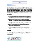
Context diagram 1
Context diagram 2
Both the above diagrams say the same thing. The second makes use of the possibility in SSADM of including duplicate objects. (In context diagram 2 the duplication of the Customer object is shown by the line at the left hand side. Drawing the diagram in this way emphasizes the Input-Output properties of a system.
The Context diagram above, and the decomposition which follows, are a first attempt at describing part of a 'Home Catalogue' sales system. In the modeling process it is likely that diagrams will be reworked and amended many times - until all parties are satisfied with the resulting model. A model can usefully be described as a co-ordinated set of diagrams.
The Top (1st level) DFD
The Top or 1st level DFD, describes the whole of the target system. It 'bounds' the system under consideration.
(To simplify the diagram some notation has been left)
Data Flow Diagrams show:
- The processes within the system
- The data stores (files) supporting the system's operation
- The information flows within the system
-
Interactions with external entities
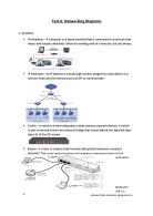
(SSADM) DFD Notations
DFDs are used in most system analysis methodologies.
Processes, in other methodologies, may also be called 'Activities', 'Actions', 'Procedures', 'Subsystems' etc.
They may be shown as a circle, an oval, or (typically) a rectangular box.
Data are generally shown as arrows coming to, or going from the edge of a process box.
SSADM (see figure) uses 4 diagramming notations (symbols) in DFDs including 2 other diagrammatic notations, 'external entities' and 'data stores', which are useful when using DFDs to describe physical or actual systems - as opposed to logical, conceptual systems.
(Note that there is no 'Decision' symbol. A decision is a Process.
The Process Symbol
Processes transform or manipulate data. Each box has a unique number as identifier (top left) and a unique name (an imperative - e.g. 'do this' - statement in the main box area) the top line is used for the location of, or the people responsible for, the process.
Processes are 'black boxes' - we don't know what is in them until they are decomposed.
Processes transform or manipulate input data to produce output data. Except in rare cases, you can't have one without the other.
Data process
A data process transforms data values.
You can make a distinction between the following types of processes:
Data Flows depict data/information flowing to or from a process. The arrows must either start and/or end at a process box. It is impossible for data to flow from data store to data store except via a process, and external entities are not allowed to access data stores directly.
Arrows must be named.
Double ended arrows may be used with care.
External Entities, also known as 'External sources/recipients, are things (eg: people, machines, organisations etc.) which contribute data or information to the system or which receive data/information from it.
The name given to an external entity represents a Type not a specific instance of the type.
When modelling complex systems, each external entity in a DFD will be given a unique identifier.
It is common practice to have duplicates of external entities in order to avoid crossing lines, or just to make a diagram more readable.
Data Stores are some location where data is held temporarily or permanently.
In physical DFDs there can be 4 types.
D = computerised Data
M = Manual, e.g. filing cabinet.
T = Transient data file, e.g. temporary program file
T(M) = Transient Manual, e.g. in-tray, mail box.
As with external entities, it is common practice to have duplicates of data stores to make a diagram less cluttered.
DFD Levels
The Context and Top Level diagrams in the example start to describe 'Home Catalogue' type sales system. The two diagrams are just the first steps in creating a model of the system. (By model we mean a co-ordinated set of diagrams which describe the target system and provide answers to questions we need to ask about that system).As suggested the diagrams presented in the example will be reworked and amended many times - until all parties are satisfied. But the two diagrams by themselves are not enough; they only provide a high level description. On the other hand, the initial diagrams do start to break down, decompose, what might be quite a complex system into manageable parts.
A revision of the example Top Level DFD
The next step - the Next Level(s)
Each Process box in the Top Level diagram will itself be made up of a number of processes, and will need to be decomposed as a second level diagram.
Each box in a diagram has an identification number derived from the parent - in the top left corner. (The Context level is seen as box 0)
Any box in the second level decomposition may be decomposed to a third and then a fourth level. Very complex systems may possibly require decomposition of some boxes to further levels.
Decomposition stops when a process box can be described with an Elementary Process Description using ordinary English, later on the process will be described more formally as a Function Description using, for example, pseudo code.
Notes
- Redrawing the diagram makes it clear that Process 3, 'Maintain Credit Rating' requires some input - if it is to produce output.
-
Note that 'Goods', while it is in reality a physical thing, is seen here as data. This is because this is a model. We will represent 'Goods' in our model by some description. In the model, 'Goods' becomes a set of data items. In the real world, there will be some physical objects, but in our model we only have an astract description.