so 01110000 ( +112)
+ 10111100 ( -68)
= 00101100 ( +44)
Multiplying: 112 * 68
112 01110000
68 01000100
112 * 4 (shift twice) 0111000000
112 * 64 (shift *6) 01110000000000
add together ( 112 * 68) 01110111000000
same as 4096 + 2048 + 1024 + 256 + 128 + 64 = 7616
Floating Point Numbers:
Using 32 bits to represent a number, positive or negative, the range of possible values is large but there are circumstances when bigger number representations are needed. The way to do this is to use floating point numbers.
A floating point number is one in which the position of the point is determined within the number itself. Working with floating point values, the position of the point in each number must be determined at processing time. This means that these calculations are much slower than fixed point. The reason for using floating point representation is that the range of possible values is much greater.
Floating point representation is similar to scientific notation and details of how values are represented vary from one machine to another. One of the standard floating point representations is the IEEE standard and it is useful to understand how this works.
The number uses a 32-bit string. This string has 3 distinct parts:
Using binary, the value of the number is:
Sign ( + / - ) 1.mantissa*2exponent
Floating Point Examples
Mantissa Exponent Value
21 0 21
21 1 210
21 2 2100
21 -1 2.1
21 -2 0.21
The Institute of Electrical and Electronics Engineers (IEEE), issued a floating point number standard, usually referred to as IEEE 754. This standard defines several formats for floating point numbers, but for simplicity the most common is shown below:
Numbers are stored in the format N=1.F* 2^(E-127), where
N = floating point number
F = fractional part in binary
E = exponent in excess 127 format, also known as bias 127 representation
This standard defines formats for representing floating point numbers and special values together with a set of floating point operations that operate on these values.
Example:
Sign bit 1 negative.
Exponent. The exponent is shown with excess 127. This means that the machine exponent is the actual exponent with 127 added. This has the effect of giving a range of 0 to 255 for the machine representation while the range of actual values is -128 to +127. If the excess was not used there would have to be a mechanism for showing a negative exponent.
In the example the actual exponent is 1000 (decimal 8).
The machine representation is:
0000 1000 (8) + 0111 1111 (127) = 1000 0111 (decimal 135)
Mantissa. The mantissa is the number being encoded. Before the number is encoded the point is moved(or floated) left or right until the value of the number is in the range:
1 < n < 2
This is known as normalisation. Since the first digit is now always going to be 1 there is no need to encode this digit. The mantissa only includes the digits after the point and the leading 1 is assumed.
The number shown above is -1.1011 0011 01*28
In un-normalised form this is -110110011.01
- Write a short account of data representation in a computer. Include details of where each format is used and consider any errors likely to occur due to inappropriate use of formats.
Most data structures are abstract structures and are implemented by the programmer with a series of assembly language instructions. Many cardinal data types (bits, bit strings, bit slices, binary integers, binary floating point numbers, binary encoded decimals, binary addresses, characters, etc.) are implemented directly in hardware for at least parts of the instruction set. Some processors also implement some data structures in hardware for some instructions — for example, most processors have a few instructions for directly manipulating character strings.
An assembly language programmer has to know how the hardware implements these cardinal data types. Some examples: Two basic issues are bit ordering (big endian or little endian) and number of bits (or bytes). The assembly language programmer must also pay attention to word length and optimum (or required) addressing boundaries. Composite data types will also include details of hardware implementation, such as how many bits of mantissa, characteristic, and sign, as well as their order. In many cases there are machine specific encodings for some data types, as well as choice of character codes (such as ASCII or EBCDIC) for character and string implementations.
The basic building block is the bit, which can contain a single piece of binary data (true/false, zero/one, north/south, positive/negative, high/low, etc.). Bits are organized into larger groupings to store values encoded in binary bits. The most basic grouping is the byte. A byte is the smallest normally addressable quantum of main memory (which can be different than the minimum amount of memory fetched at one time). In modern computers this is almost always an eight bit byte, so much so that many skilled programmers believe that a byte is defined as being always eight bits. In the past there have been computers with seven, eight, twelve, and sixteen bits. There have also been bit slice computers where the common memory addressing approach is by single bit; in these kinds of computers the term byte actually has no meaning, although eight bits on these computers are likely to be called a byte. Computers use this type of memory to store lots of different types of information, including numbers, text, sounds and graphics such as still images and videos etc.
There are different types of number systems used:
-
Binary number system using only ones and zeros (or two states).
-
Decimal number system based on ten digits (including zero).
-
Hexadecimal number system based on sixteen digits (including zero).
-
Octal number system based on eight digits (including zero).
-
Duodecimal number system based on twelve digits (including zero).
If these were mixed up, or the wrong type of number system was used, the data would be interpreted wrongly, thus causing errors etc.
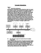
- Using a detailed block diagram and brief comments, describe the function of the components of a typical microprocessor system.
RAM – Random Access Memory
RAM contains bytes of information, and the microprocessor can read or write to those bytes depending on whether the RD or WR line is signalled. One problem with today's RAM chips is that they forget everything once the power goes off. That is why the computer needs ROM.
ROM – Read Only Memory
A ROM chip is programmed with a permanent collection of pre-set bytes. The address bus tells the ROM chip which byte to get and place on the data bus. When the RD line changes state, the ROM chip presents the selected byte onto the data bus.
- Describe the “fetch-decode-execute” cycle for an instruction in a microprocessor. Relate the basic actions of the cycle to the internal operations of the microprocessor system.
The fundamental sequence of steps that a CPU performs - it is the time in which a single instruction is fetched from memory, decoded and executed. The first half of the cycle transfers the instruction from memory to the instruction register and decodes it. The second half executes the instruction. This can be described in a few steps:
- Fetch the Instruction from Main Memory - The CPU presents the value of the program counter (PC) on the address bus. The CPU then fetches the instruction from main memory via the data bus into the Current Instruction Register (CIR), a circuit that holds the instruction so that it can be decoded and executed.
- Decode the Instruction - The instruction decoder (ID) interprets and implements the instruction
- Fetch Data from Main Memory - Read the effective address from main memory if the instruction has an indirect address. Fetch required data from main memory to be processed and placed into registers.
- Execute the Instruction - From the instruction register, the data forming the instruction is decoded by the control unit. It then passes the decoded information as a sequence of control signals to the relevant function units of the CPU to perform the actions required by the instruction such as reading values from registers, passing them to the Arithmetic logic unit (ALU) to add them together and writing the result back to a register. A condition signal is sent back to the control unit by the ALU if it is involved.
- Store Results - The result generated by the operation is stored in the main memory, or sent to an output device. Based on the condition feedback from the ALU, the PC is either incremented to address the next instruction or updated to a different address where the next instruction will be fetched. The cycle is then repeated.
- Write assembly language code that will fetch a data byte from memory, add it to another data byte in memory and store the result in memory. Verify the action of your code using an appropriate software package.
start = $0800 //sets the start address
num1 = 6 //defines num to be added
num2 = 4 //defines next num to be added
loc1 = $0850 //defines a memory location
loc2 = $0851 //defines another memory location
ans = $0852 //defines location to save
.ORG start
LDA #num1 //the accumulator is loaded with a predefined value
STA loc1 //that value is then copied from the accumulator into location in memory
LDA #num2 //the accumulator is loaded with another predefined value
STA loc2 //that value is then copied from the accumulator into location in memory
LDA loc1 //the initial value is fetched from memory and loaded into the accumulator
ADC loc2 //the other value is fetched from memory and added to the accumulator
STA ans //the end result is then stored into memory
.END
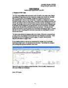
- Extend the scope of your code in Q7 to allow a block of data ( 8 bytes) in memory to be summed and the final sum stored in memory. You must include a flow diagram and comprehensive comments explaining the action of your code.
Start = $0800 //sets the start address
Number = 8 //sets number to 8
.ORG start
main LDX #0 //load X register immediate - 0
LDA table,x //load accumulator indexed - x
LDY #number //load Y register with number immediate
Again JSR sub1 //jump to subroutine
DEY //decrement the Y register
BNE again //branch if zero flag clear
STA answer //store accumalator
Here JMP here //jump to another location
sub1 INX //increment the X register
ADC table,x //add with carry
RTS //return from subroutine
Table .DB 5,10,15,20,25,30,35,40
Answer = table+number