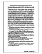
Overleaf shows a picture of a schematic diagram for a Kodak camera.
The next step to making a printed circuit board is to design the artwork of the printed circuit board. The artwork (or layout) is the pattern that is to be etched in the copper. The artwork can be produced in many ways also; the traditional and popular method is by using special opaque press on or rub on patterns, which are laid out on drafting film-using tapes. There are now new methods being used, computer aided design is beginning to replace the manual methods of artwork. With computer aided design the artwork can be printed or plotted onto paper or transparent film. This is the method that would be used for the board shown. The artwork would be printed onto a transparent film; a piece of overhead projector paper would also be suitable.
The third step is to transfer an image of the artwork to a copper coated circuit board. The image that is to be transferred to the circuit board must be etch resistant in order for it not to react with the chemical solution used for etching the pattern. As with all aspects of making a printed circuit board, there are many methods available to use to transfer the image to the circuit board. The simplest is to apply rub-on or press on patterns directly to the copper. With the specific board type which is shown, the most suitable method is to use photographic techniques, which expose onto the board, and due to the layer of photo-sensitive etch resistant material the image will de develop on the board. This works by first peeling off the protective coating in a dim light, and then exposing the board, which has the transparency image in place on the board, and al fixed together using a glass plate, and then exposing the circuit board to ultra violet light. A special developer is needed (or sodium hydroxide mixed with water) next, as you need to submerge the board in the liquid. After approximately three minutes the image should be visible and on the exposed parts copper should be seen. This method works to expose selective parts necessary because when the board is put in the developer the coat will be dissolved where the lights affected the board. Therefore the areas, which remain are etch resistant.
Overleaf shows a photo of an image that has been transferred onto a transparent film using a computer application called eagle.
The next step is etching. In this stage removing the exposed copper creates the final Printed Circuit Board. In order to etch the board, it must be sub merged in an etchant (a chemical solution, which removes the exposed copper from the board). Two etchant solutions commonly used are ferric chloride and ammonium persulfate. Using ferric chloride is cheaper and doesn’t need to be heated for it to work. Ferric chloride is an orange liquid, which turns a dark brown colour as it absorbs the copper during the etching process. In order for etching to be successful, it must be done quickly, to stop the chance of the etchant undercutting, or removing copper under the edges of the etch resistant. Below shows a picture of a printed circuit board which has been etched.
The main methods to speed up the etching process are by agitating, heating or aerating. Once the etching process is complete you should be able to see bare board show through the copper. The board must be thoroughly rinsed and dried. If the board is made successfully then the layer of photo-resist must be removed. This can be done using acetone.
After the etching process is complete then the printed circuit board is ready for drilling, where the board is drilled for component and mounting holes. Then soldering can be done, where the components are mounted onto the board and soldered to their pads. The printed circuit board is then ready for testing, installing and using.
Printed circuit boards are provided and produced in many different stages, and each of these stages has many different construction offers. Making printed circuit boards can be cheap and quick but it can also be a long process and can be expensive.
The methods explained for mass-production. Time is needed in designing the artwork, but this only needs to be designed once, whereas the other stages, such as transferring the image, drilling, soldering etc can be done using batch or assembly line methods, therefore the more boards you make, the less time is spent per board.
Printed Circuit Assignment
Product design BSc
Applied technology
Jeanette Griggs
20089227