The Waterfall Model (6,10)
The Waterfall Model was the first published model of the software development process and it was derived from other engineering processes. (Royce, 1970)
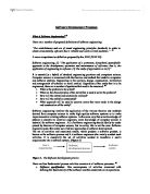
Figure 2. The 5 stages of the Waterfall Model
The name of this model is derived from the characteristic cascade from one phase to another. As we can see from the diagram, there are 5 distinct stages in the Waterfall Model. On completion of each stage, it is ‘signed off’ and development commences to the following stage:
-
Requirement analysis and definition: Through consultation with system users, the system, services, constraints and goals are established. These are then defined in greater detail and serve as a system specification.
-
System and software design: This stage partitions the requirements into either hardware or software systems. An overall system architecture is established. The software design involves identifying and describing the fundamental software system abstractions and their relationships.
-
Implementation and unit testing: During this stage the software design is realised as a set of programs or program units. Unit testing entails verifying that each unit meets its specification.
-
Integration and system testing: To ensure that the software requirements have been met, the individual program units or programs are integrated and tested as a complete system. On completion of these tests, the software system is then delivered to the customer.
-
Operation and Maintenance: At this stage, the system is installed and put into practical use. Maintenance involves correcting those errors, which were not discovered in earlier stages of the life cycle. Improving the implementation of system units and enhancing the system services as new requirements are discovered.
The results from each phase are one or more documents which then need to be approved. The diagram suggests that the following stage cannot commence until the completion of the previous one. However, in practice, this is rarely the case, as the stages overlap and feed information to each other. During design, problems with requirement may be indicated and identified and during coding, problems with the design may be encountered. This model is not a simple linear process as the diagram would suggest but rather it involves a series of iterations of the development activities.
There are a number of problems identifiable with this approach. Because of the cost of producing and approving documents iterations are costly and involve considerable rework. As a result it is quite normal to freeze parts of the development process and to continue with later stages. Problems are often left for later resolution, totally ignored or worked around. The unnatural partitioning of the project into these distinct stages means that development is very rigid and inflexible making it very difficult to incorporate new user requirements. Commitments need to be made at an early stage and hence the complete system has to be very well understood at this early stage in order to produce the desired product. It was problems such as these that paved the way for new, replacement technologies many of which were based on object oriented principles that were seen to overcome many of the problems associated with these structured approaches.
Object-oriented analysis and design (OOAD) (5,9)
Analysis emphasises an investigation of a problem and its requirements rather than a solution. For example, if a new computerised banking system were required, the question would arise; how will it be used? Design, on the other hand emphasises a conceptual solution that fulfils the derived requirements rather than its actual implementation. For example, a database schema and software objects. These designs can ultimately be implemented. Analysis and design have been best summarised in the phrase:
“Do the right thing (analysis) and do the thing right (design).”
During object oriented analysis there is an emphasis on finding and describing the objects in the problem domain. So, in the case of the banking system some of the objects would include customers, cash, and cheques. During object-oriented design there is an emphasis on defining software objects and how they interact to achieve the desired requirements. Once again looking at our banking system, an account software object may have a balance attribute and a getbalance amount() method. During the implementation stage, in an object-oriented language such as Java we would see the implementation of design objects such as an account class.
The Unified Process (UP) (4,8)
As mentioned earlier, the Unified Process is an example of an object-oriented software process. It is, however much more than a single process; it is a generic process framework that can be specialised for a very large class of software systems, for different application areas, different types of organisations, different competent levels and different project sizes. The Unified Process is component based and hence the software system being built up is made up of smaller components all linked together through well-defined interfaces. The Unified Process uses the Unified Modelling Language (UML) when preparing all blueprints of the software system. UML is an integral part of the Unified Process as they were developed hand in hand. (We will deal with UML further on in this paper). The real distinguishing aspects of the Unified Process, which make it so unique is the fact that it is; use-case driven, architecture-centric and iterative as well as incremental. Let us now look at theses three properties in slightly greater detail:
-
Use-case Driven:(3) When building a software system we need to know what its prospective users want and need. We think of users, not only does it mean humans that are going to use the system but also other systems which may need to interact with this system. So, going back to our electronic banking example used earlier, if we think of a cash-point machine, we can see that a user interacts with this machine, providing it with certain information (some stored on the users card and others which the user has to manually provide, i.e. the pin code) and in response to this information the system performs a sequence of actions, e.g. displaying the users account balance. This whole interaction is known as a use-case. It is a piece of functionality in the system that gives the user a result of value. All the use-cases collectively make up complete functionality of the system. This notion of using use-cases to define a system has the effect that when looking at system functionality a push is made towards designing functions that are needed by individual users rather than ad hoc functions, which may be good to have. Not only are use-cases a tool for system requirement specification; they also drive the development process. Now, returning to the unified process we can see that the use-case driver means that the unified software development process follows a flow; i.e. it proceeds through a series of workflows that are derived from the use-cases. As a result use-cases are specified, designed and are ultimately the source from which the testers construct the test cases.
Architecture-centric:(4) In software terms architecture is a reference to the different views of the system being built in much the same way that a building architect looks at a building from different viewpoints e.g. structure, plumbing, electricity and so forth. The most significant static and dynamic aspects of the system are embodied in the software architecture concept. The architecture expands out of the needs of the enterprise as sensed by users and as reflected in the use-cases. There are however other factors of influence e.g. computer architecture, operating system etc. Architecture is a view of the whole system with greater emphasis on the more important characteristics being made by leaving less important details aside. Since this is a judgemental approach based solely on the persons making the judgement the value of such an approach is dependant on the persons assigned to the task. If the unified process is truly use-case driven there must surely be a relationship between architecture and use-cases. The relationship is of the chicken & egg form where use-cases when realised must fit into architecture and architecture must allow room for realisations of all the required use-cases now and in the future. Hence, there must be synchronous evolution of architecture and use-cases. This is achieved in the unified process by defining an architecture around the key use-cases of the system. These key use-cases may only amount to some 5-10% of all the use-cases but it ensures the development of the system with the core system functions.
Iterative & Incremental:(9) Several best practices are promoted by the unified process but one stands above the others; iterative development. Development is organised into a series of short, fixed-length smaller projects known as iterations. The output from each iteration is a tested, integrated and executable system. Each iteration has associated with it its own requirements, analysis, design, implementation and testing activities. The iterative lifecycle is based upon the successive enlargement and refinement of the software system through multiple iterations with cyclic feedback and adaptation as core drivers to converge upon a suitable system. The system goes through a complete development cycle in each iteration and it grows incrementally over time iteration by iteration so that the initial iterations will be much smaller in size to the later iterations nearing the completed system. The output from each iteration is not simply an experimental prototype but rather a production grade subset of the final system. In general each new iteration deals with new requirements but this is not the rule as an iteration may on occasion revisit an existing subsystem in order to improve it rather than extending it with new features.
There have been a number of variations to the Unified Process, but in essence they are all very similar encompassing the afore mentioned properties and consisting of the same phases. In particular the Rational Unified Process (RUP) has been adopted (Kruchten ‘00) which is a detailed refinement of the Unified Process.(11)
The RUP project organises the work and iterations across four major phases and each phase is concluded with a well-defined milestone i.e. a point in time at which certain critical decisions must be made and therefore key goals must have been achieved:
Inception: During this phase you establish the business case for the system and delimit the project scope. All external entities with which the system will interact have to be identified and the nature of this interaction needs to be defined at a high level. This involves the identification of all new use-cases and describing the key ones. The business case includes success criteria, risk assessment, resource estimation and phase plans detailing the dates of major milestones. Some of the outputs from this phase include:
- a vision document (details of the core project’s requirements, key features & main constraints)
- an initial use-case model (10-20% complete)
- an initial risk assessment
- a project plan showing phases and iterations
- one or several prototypes
Elaboration: This is arguably the most important of the four phases, the purpose of which is to analyse the problem domain, develop the project plan and eliminate the highest risk elements of the project. In order to accomplish these objectives a detailed knowledge and understanding of the whole system is needed. Some of the outputs from this phase include:
- a use-case model (at least80% complete)
- a software architecture description
- an executable architectural prototype
- a revised risk list and business case
- a preliminary user-manual
Construction: All remaining components and application features are developed and integrated into the product during this stage and all features are thoroughly tested. Some of the outputs from this phase include:
- the software product integrated on the adequate platforms
- user manuals
- a description of the current release
Transition: The purpose of this phase is to transition the software product to the user community. Issues usually result from this which require you to develop new releases, correct certain problems and finish features which were postponed. The primary objectives behind this phase include:
- achieving user self-supportability
- achieving final product baseline as rapidly and economically as possible
Compared to the traditional waterfall process model, described earlier, the iterative unified process has a number of distinct advantages particularly in the area of risk identification and management. Its risk-driven approach means that if the project fails, it does so at a very early stage rather than later on after heavy cost have been incurred. This is achieved by focusing on designing, programming and proving the essential software components and architecture for high risk components in early iterations and leaving easier tasks for later iterations. This, as opposed to the waterfall model where high risk tasks are undertaken very late in the development process thus associating a greater revenue loss with failed projects. The iterative process also makes changes in requirements easier to incorporate into product development and also allows for a higher level of reuse as well as producing a product with better overall quality.
Additionally the breakdown of the iterations into distinct phases and the criteria of each phase serves to enhance the software development process. For instance the inception phase serves as a feasibility phase where just enough investigation is done to support a decision to continue or stop and elaboration is a phase where core architecture is iteratively implemented and high risk issues are mitigated.(9)
The Universal Modelling Language (UML)(7)
UML specifies a set of diagrams and notational conventions for modelling systems using an object-oriented paradigm and it can be used to model different kinds of systems ranging from software to organisational processes. It is a completely language independent notation allowing the specification of classes, their data or attributes, methods, inheritance and other more general relationships between classes(2). Not only does it have excellent support for pure object oriented languages such as Java and C# it also supports hybrid object oriented languages such as C++ and even object based languages such as Visual Basic. It is important to realise that UML is distinct from UP in that it does not give us any kind of software modelling methodology it is simply a notation. UML is not linked to any one methodology or lifecycle and it can be used with practically all existing methodologies. However, UP is in some ways tied to UML as this is its preferred underlying visual modelling syntax. Just like UP the goal of UML is to support and encapsulate best practices in software engineering based on the experiences of the last decade. To do this UML and UP have unified the best parts of previous attempts at visual modelling notations and software engineering processes. The basic premise of UML is that software systems and indeed other systems can be modelled as collections of collaborating objects. Not only does this fit in with object oriented software systems and languages but also for business processes and other applications. There are 2 parts to a UML model:
-
Static structure: This describes what types of objects are critical to the system and their interactions
-
Dynamic Structure: This describes the lifecycles of these objects and how they collaborate together to deliver the desired system functionality.
UML provides nine different diagrams with which to model the software development process:
-
Use-case diagrams: To describe business processes
-
Sequence diagrams: To describe time dependencies and other events
-
Collaboration diagrams: To describe the interactions within a system
-
State diagrams: To describe the behaviour of system objects
-
Activity diagrams: To describe the behaviour of use-cases, objects and operations
-
Class diagrams: To describe the static structure of classes
-
Object diagrams: To describe the static structure of objects
-
Component diagrams: To describe components
-
Deployment diagrams: To describe the productive deployment of a system
Together these nine different types of diagrams give UML the capacity to model a complete software development process from requirements engineering to implementation.
Bibliography
- Baner, F.L software engineer information processing, 71, 1972
- Grady Booch, Ivar Jacobson and James Rumbaugh, Unified Modelling Language 1.3, White paper, Rational Software Corp., 1998
- Ivar Jacobson, Magnus Christerson, Patrik Jonsson and Gunnar Övergaard, Object-oriented Software Engineering-A use case driven approach, Wokingham, England, Addison-Wesley, 1992, 582p.
- Ivar Jacobson, Grady Booch, and Jim Rumbaugh, Unified Software Development Process, Addison-Wesley 1999.
- Sjaak Brinkkemper, Geertvan den Goor and Shuguang Hong, A Formal Approach to the Comparison of Object-oriented Analysis and Design Methodologies
-
Ian Sommerville, Software Engineering, 6th Edition
-
Mark Collins-Cope, Object Oriented Analysis and Designed Using UML,
White paper, Ratio group.
-
Jim Arlow, Ila Neustadt, UML and the Unified Process: Practical Object-oriented Analysis and Design.
-
Craig Larman, Applying UML and Patterns, 2nd edition
-
R S Pressman, Software Engineering, A Practitioners Approach, 5th Edition
- Rational Unified Process: Best Practices for S/Ware Development Teams