- Mesh Topology
The type of network topology in which each of the nodes of the network is connected to each of the other nodes in the network with a point-to-point link – this makes it possible for data to be simultaneously transmitted from any single node to all of the other nodes. Meshes are often used to screen out unwanted things, such as insects. Wire screens on windows and mosquito netting can be considered as types of meshes. Wire screens can also be used to shield against radio frequency radiation, i.e., in microwave ovens and Faraday cages.
There are two types of mesh topologies: full mesh and partial mesh.
Full mesh topology occurs when every node has a circuit connecting it to every other node in a network. Full mesh is very expensive to implement but yields the greatest amount of redundancy, so in the event that one of those nodes fails, network traffic can be directed to any of the other nodes. Full mesh is usually reserved for backbone networks.
Partial mesh topology is less expensive to implement and yields less redundancy than full mesh topology. With partial mesh, some nodes are organized in a full mesh scheme but others are only connected to one or two in the network. Partial mesh topology is commonly found in peripheral networks connected to a full meshed backbone.
D4 Explain what is meant by network access and control methods. Describe various methods by which access can be gained.
Network Access Control (NAC) is a method by which access to enterprise network resources is granted based upon authentication of the user and device as well as verification of the device's compliance to policy. NAC aims to do exactly what the name implies: control access to a network. The term NAC is also sometimes used for Network Admission Control, which is focused on authenticating users and performing a posture check on the connecting device. The broader definition of NAC, as access control, includes pre-admission endpoint security policy checks and post-admission controls over where users can go on a network and what they can do.
Data transmission is complex by collisions that happen within a network when two or more signals are sent out at the same time. There are few ways to overcome this difficulty.
There are two ways of data flow control;
Collision Avoidance (CSMA)
CSMA is about how data signals find there way from users computer onto a network system without colliding with the thousands of other signals that are also on the network.
In computer networking, CSMA belongs to a class of protocols called multiple access methods. CSMA stands for: (Carrier Sense Multiple Access). In CSMA, a station wishing to transmit has to first listen to the channel for a predetermined amount of time so as to check for any activity on the channel. If the channel is sensed "idle" then the station is permitted to transmit. If the channel is sensed as "busy" the station has to defer its transmission. This is the essence of the "collision avoidance" part of the protocol.
After waiting for a sufficient time for all stations to receive the jam signal, the data station transmits a frame, and while transmitting, if the data station detects a jam signal from another station, it stops transmitting for a random time and then tries again.
Collision Detection (CSMA)
CD (collision detection) defines what happens when two devices sense a clear channel, then attempt to transmit at the same time. A collision occurs, and both devices stop transmission, wait for a random amount of time, and then retransmit. This is the technique used to access the 802.3 Ethernet network channel. This method handles collisions as they occur, but if the bus is constantly busy, collisions can occur so often that performance drops drastically.
It is estimated that network traffic must be less than 40 percent of the bus capacity for the network to operate efficiently. If distances are long, time lags occur that may result in inappropriate carrier sensing, and hence collisions.
To understand the theory of CSMA/CD, imagine you are with a group of friends and having a discussion. Each of your friends could be classified as a device on the network. At any one point in time only one person will be speaking (transmitting), and others will be listening (receiving). When one person finishes talking, the other people will see a blank spot in the speech and attempt to speak, and so keeping the conversation going.
If two people attempt to talk at the same time (collision), then both will stop, and then will wait for a random period (back off algorithm) of time before speaking again. This will ensure that both get to say what they want to say, but one at a time and with no overlapping of what they are trying to say.
Task 6: P6-identify and describe the basic role of a range of interconnection devices. M3 - understand the selection criteria for LAN interconnection devices.
I will describe the role of the basic of a range of interconnection devices and how each of them works within network system.
HUBs
Hubs are probably the most common part of network hardware in Ethernet networks. They connect a number of computers (frequently 8 or 16) together in a star topology. Computers are connected to the hub using UTP cables with RJ45 connectors at each end. A hub simply takes the signal sent from each computer, intensifies it and transmits it to all the other computers attached to the hub. An RJ45 socket is used to connect the hub to another hub, therefore providing a way to increase the number of computers on the network.
An Ethernet hub, or repeater, is a fairly unsophisticated broadcast device. Hubs do not manage any of the traffic that comes through them, and any packet entering any port is broadcast out on every other port (every port other than the port of entry). Since every packet is being sent out through every other port, packet collisions result--which greatly impedes the smooth flow of traffic.
Dual Speed HUBs
Back in the days Fast Ethernet switches were relatively expensive devices. However Hubs suffered from the problem that as simple repeaters they could only support a single speed. Whilst normal PCs with expansion slots could be easily upgraded to Fast Ethernet with a new network card, computers with less common expansion mechanisms, or no expansion bus at all, and other equipment, such as printers, could be expensive or impossible to upgrade. Therefore, a compromise between a hub and a switch appeared known as a dual speed hub. These split the network into two segments, each acting like a hubbed network at its respective speed with a two-port switch between them. Therefore they allowed mixing of the two speeds without the cost of a Fast Ethernet switch.
Usefulness
Historically, the main reason for purchasing hubs rather than switches was price. This has largely been eliminated by reductions in the price of switches, but hubs can still be useful in special circumstances:
- A Protocol Analyzer connected to a switch does not always receive all the desired packets since the switch separates the ports into different segments. Connecting the protocol analyzer to a hub allows it to see all the traffic on the segment. (Expensive switches can be configured to allow one port to listen in on traffic on another port. However, these cost much more than a hub.)
- Some computer clusters need each member computer to receive all of the traffic going to the cluster. A hub will do this naturally, using a switch requires implementing special tricks.
- When a switch is available for end users to make connections, for example, in a conference room, an inexperienced or careless user can bring down the network by connecting two ports together, causing a loop. This can be prevented by using a hub, where a loop will break other users on the hub, but not the rest of the network. (It can also be prevented by buying switches that can detect and deal with loops, for example by implementing the Spanning Tree Protocol).
- A cheap hub with a 10BASE2 port is probably the cheapest and easiest way to connect devices that only support 10BASE2 to a modern network (cheap switches don't tend to come with 10BASE2 ports). The same goes for linking in an old thicknet network segment using an AUI port on a hub (individual devices that were intended for thicknet can be linked to modern Ethernet by using an AUI-10BASE-T transceiver).
Switches
Switches look very much like hubs and on the surface they perform the same function, i.e. they connect a number of computers together in an Ethernet LAN. However, hubs are ‘dumb’ devices; they simply receive a message, intensify it and broadcast it to all the other computers that are connected to the hub. Switches are ‘intelligent’; they inspect the message sent from one computer, recognize the computer to which it is being sent and transmit the message only to that computer, not all the others connected to the switch. The benefit of this is that network traffic is significantly reduced, which reduces the prospect of collision occurring. Switches are slightly more costly to buy than hubs but, of their capability to improve the performance of the network, they are normally used in favourite to hubs.
Switches vs HUBs – Which one is better?
If you have anything more than one computer with a dial-up phone connection, you likely to have your computer connected to other equipment using Ethernet. Your setup could be as simple as one computer connected to a cable modem or DSL modem using Ethernet. If you have multiple machines, you either have a router with multiple ports (Ethernet connectors), a switch or a hub. If you have a router, it's simply a special case of being either a switch or a hub. So, really, there are only two things to talk about here--switches and hubs.
Ethernet allows multiple connections to what you might call a common wire. In early Ethernet implementations, "common wire" wasn't only a descriptive term; it was how connections actually worked. That is, each computer tapped into this single wire.
The hub come the closest to being an ordinary junction box. It has electronics to deal with signal levels and collision detection, but it really does no more than pass along what it receives to all the other ports (connections) on the hub.
A switch, on the other hand, is more intelligent. It is selective about where it passes data. That is, it learns (or is told) where certain equipment is located and passes along the data only to the ports that need to receive it. The big advantage here is if you have a busy network where not all of the traffic is destined for a particular connection--a server, for example. In this situation, the switch allows multiple interactions at once. For example, if your Internet connection is on port 1 and your server is on port 5, the traffic from a local machine on another port, say 3, to the Internet appears only on ports 1 and 3. Therefore, this traffic does not interfere with traffic to your server on port 5 from other machines.
You probably are thinking now that a switch is always the best answer. That is, if the slight additional cost of a switch is not an issue, you may be thinking you should just buy a switch. In truth, however, a switch is not always the best answer.
To get around this confusing situation, most modern hubs and switches sense the signals on each cable and internally connect the right pairs. That is, it all works without human intervention. This feature alone can save you a lot of time and headaches.
After looking at the case of which one is better, Switch or HUB, I would recommend Switch device over HUB device and reason for that is clearly explained in above paragraphs.
Repeaters
Repeaters are rather like two-port hubs. They have just two RJ45 sockets and are mainly used as a way of extending cable lengths. Ethernet has limits on the length of cables that can be used (about 100 meters) and repeaters can be used to increase this distance. However, even with repeaters, there is an absolute maximum of around 1000 meters. Like hubs repeaters are dumb devices. Whatever signals they receive they simply amplify and send on.
Repeaters can have a number of ports and with a little imagination it is possible to build quite complex and large networks using only repeaters.
If a repeater sees a collision on a cable segment, the repeater detects this in the normal way, and then generates a JAM signal to all connected output ports. This ensures that every computer connected to the LAN is aware of the collision, and does not try to transmit during the collision period.
Bridges
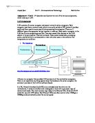
Bridges appear to work very much like repeaters, but just as switches are intelligent versions of hubs, bridges are intelligent versions of repeaters. Bridges are used to interconnect two separate LANs, perhaps on different floors of a building. They listen to the network traffic and learn which destination address is located on which LAN. Using this information they filter the messages they hear on each LAN and only pass across the messages that need to be transferred between the LANs.
To learn which addresses are in use, and which ports (interfaces on the bridge) theory is closest to, the bridge observes the headers of received Ethernet frames. By examining the MAC source address of each received frame, and recording the port on which it was received, the bridge may learn which addresses belong to the computers connected via each port. This is called "learning". In the figure above, consider three computers X, Y, Z. Assume each sends frames to the other computers. The source addresses X, Y are observed to be on network A, while the address of computer Z will be observed to be on network B.
Connecting bridges and switches together
There is a special rule controlling the interconnection of bridges and switches, as there is for Ethernet Hubs. The rule says simply, that a bridge / switch /hub LAN must form a tree, and not a ring. That is, there must be only one path between any two computers. If more than one parallel path were to exist, a loop would be formed, resulting in endless circulation of frames over the loop. This would soon result in overload of the network. To avoid this happening, the IEEE has defined the Spanning Tree Algorithm (STA) which automatically detects loops and disables one of the parallel paths. The Spanning Tree Algorithm may also be used to build fault-tolerant networks, since if the chosen path becomes invalid, due to a cable / bridge / switch fault, and an alternate path exists, the alternate path is enabled automatically.
Routers
They carry out a similar task to bridges but they do it differently. Bridges operate at the OSI link layer while routers operate at the network layer. Routers examine each packet, remove the destination address and use this to route the packet from one LAN to another. Routers pass information between each other and build their own routing tables that contain information about the best routes to various destinations through a compound network of many LANs.
A router introduces delay (latency) as it processes the packets it receives. The total delay observed is the sum of many components including:
- Time taken to process the frame by the data link protocol
- Time taken to select the correct output link (i.e. filtering and routing)
- Queuing delay at the output link (when the link is busy)
- Other activities which consume processor resources (computing routing tables, network management, generation of logging information).
The router queue of packets waiting to be sent also introduces a potential cause of packet loss. Since the router has a finite amount of buffer memory to hold the queue, a router which receives packets at too high a rate may experience a full queue. In this case, the router ahs no other option than to simply discard excess packets. If required, these may later be retransmitted by a transport protocol.
Architecture of a router
The layer of the OSI model that each of the network devices operates at is shown in table below.
Network devices and their relationship to the 7 – layer model
Task 7 - P7-distinguish between the Internet and the worldwide web and describe a range of services they provide.
Internet
The Internet has become the best known network. It spans the globe, connects millions of computers and is changing the way we do all sorts of things, from shopping to communicating with friends and family. The Internet provides a range of facilities such as email, the World Wide Web (www), file transfer, music, films, msn and file transfer.
Concepts of Internet communication
Most of us connect to the Internet by a modem or telephone wire, although broadband connections using a digital surface are becoming more popular. Whatever method is used, the connection is made to a company called an ISP (Internet service provider). ISPs are connected to each other and large ISPs maintain connections using fibre optic cables for a whole country or region. These, in turn are connected to ISPs in other countries. In this way, the entire Internet is made using the TCP/IP protocol. TCP/IP (transmission control protocol / Internet protocol) is actually a whole suite of protocols which control how computers communicate on the Internet and many other networks including LANs.
Computers connected to the Internet can be divided into clients and servers. When you connect to the Internet and view various web pages, you are acting as a client. The web pages you are viewing are being sent to your client machine from computers which act as servers.
For example, if you are viewing the Liverpool football club’s website at your computer connects to a computer, probably a group of computers at the Liverpool where those pages are held. Your computer requests the particular page you wish to see on the Liverpool website and the Liverpool’s computer sends the page. Like all the networks, the Internet uses a variety of different protocols. The transfer of web pages is achieved using HTTP (hypertext transfer protocol.)
If you know the URL of the website, such as then you can just type that into your web browser. However, what happens ‘behind the scenes’ is a little more complex. Every computer on the Internet is assigned a unique address called an IP (Internet Protocol) address. IP addresses are 32 – bit numbers that are normally shown as four numbers, each of which can be in the range 0 to 25. So a typical IP address would look like this: 255.255.10.12.
This works fine as long as the user knows the URL of the website but some times the user might want to find out some information like, cheap airline flights, without knowing the URL of any suitable websites. In this situation, search websites provide a method of finding the required information. Some websites still exist and the most famous one’s are as follow;
Many search websites have a server that runs in the UK as well as the in USA and other countries. If you are looking for flights from the UK to Europe, then it is best to search on . If you are looking for information on the wilds animals, you may find more world wide information if you search on .
Task 7 – D2
Set up a PC to communicate via the Internet using appropriate hardware and software that will enable web browsing and file transfers.
System Requirements
To connect to the internet, there are number of requirements. First and foremost, you need a computer, either a PC with the Windows XP, ME or 98 or 95 operating system, or an Apple Macintosh. As well as installing necessary network protocols such as TCP/IP on the computer, some application software is required. For viewing web pages, a web-browser such as Microsoft Internet Explorer is required. For sending and receiving non-web-based email, an email program such as Microsoft Outlook is needed. To use FTP you must have an FTP program.
Installation Process
I will now install Internet modem to the computer and the Operating system I will be doing on is Windows 98. I will explain all my setup step by step with images showing the proof.
Step 1
This is the 1st step towards installing Internet connection on the computer. The system is configuring some specific suffix, e.g. IP address and subnet mask. After configuring important tools, following screen appeared on the system.
Step 2
This screen is telling me to click on next button, so the system can carry on installing the Internet connection. The is just letting me know that “Network Connection Wizard” application will enable me to send and receive emails, share files, web browsing and print the documents, etc. When I clicked on next button, following page appeared on the screen.
Step 3
This screen is telling me to choose a type of connection that I want to create, based on my network configuration and my networking needs. I chose the 1st option, which is “Dial up to private network”, which connects you to Internet through phone line modem or ISDN. When I clicked on next button system showed following page on my screen.
Step 4
The system is asking me to type in the phone number of the computer or Network which I want to use to connect. I typed in 456 in phone text box and following screen appeared on my computer.
Step 5
The system is asking me to choose an option from the connection availability screen. I am allowed to make new connection to all users or just to my self. If I choose it just for myself, connection will not be available until I log on to the PC. I chose connection for all users’ option and clicked on next button. System showed me following screen on PC.
Step 6
Network and dial-up connections screen is asking me to choose one of the options from the following options. I can choose from “Make a new connection, AAA, Local area Connection or Computer 1”. I chose Computer 1 as an option and the following screen appeared on my system.
Step 7
Connect computer 1 screen is asking me to choose user name and password and then click on dial button to connect to the Internet. After selecting my user name and password, I clicked on dial button as I was told by the system to do so. Following screen appeared on my system.
Step 8
Virtual Modem screen is telling me to wait for the connection to be made. System is waiting for incoming connection on TCP port 28800 on Virtual modem. After a while system showed following screen on my PC.
Step 9
This screen shows Network Area Connection status, which shows that connection is made and the speed of the Internet is, 10Mbps, so therefore my installing progress in completed and it is Internet Connection is successfully installed on the PC. I can now use the Internet.
Final Conclusion
To use FTP software, user must know the URL of an FTP server, and have a valid FTP user name and password. Once you have successfully logged on to an FTP server, you can transfer files to and from the server.