AIM
Research, design and build an electric AC generator. Control and record the effects of changing two variables (varying the space between the magnets and the armature, the velocity of relative motion between the coil and the magnets).
HYPOTHESIS
- As we spin the coil relative to the magnets, the coils should created an electric current that lights up our light bulb or makes movement on the galvanometer.
- The more coils we add, the greater the current produced when in action.
- The closer the magnets relative to the armature, the greater the magnetic field on the armature and the greater the current produced when in action.
- The faster the velocity of relative motion between the coil and the magnets, the greater the current produced.
EQUIPMENT
- 2 Magnets (to produce a magnetic field in the coils)
- Insulated copper wire (for the current to flow through)
- Wood block (for the base)
- Metal axel (for the armature to spin on)
- Wood core (cylinder shape to act as the armature)
- 2 thin metal rectangular pieces (act as the brushes)
- 2 metal slip rings (to connect to the brushes)
- Light Bulb (test if its producing current)
- Tape and glue (stick stuff together)
- 2 small wood pieces (to support the axel at either end)
- Electric hand drill (spin the generator)
- Galvanometer (test the current)
METHOD
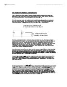
- Construct all the parts together as in the diagram below.
- Make a hole in the middle of the cylinder shape wood piece and put the axel through that hole (the wood piece should be near the end of the axel as seen in the diagram below). Glue the ends so it doesn’t move (see diagram).
- Wrap 50 times around the wooded piece (armature) the insulated copper wire and hold it in place with the tape or glue (see diagram).
- Glue the two metal slip rings to the axel. Connect one end of the copper wire to one of the slip rings and the other end to the other slip ring (see diagram)
- Make a hole in both the small pieces of wood to support the axel at either end. Glue the pieces to the big block base wood (see diagram).
- Get the two thing metal pieces (brushes) and bend the tips of one end for each brush. Glue each one down to the base under a slip ring each so that they just touch (see diagram).
- Connect one a wire from the bottom of a brush to the positive hole of the light bulb and another wire from the other brush to the negative hole of the light bulb (see diagram).
- Glue down the light bulb to the base (see diagram).
- Position the two magnets on opposite sides of the armature (3 cm away) so that a north pole faces a south pole (see diagram).
- Now you are ready to test it. Connect wires from the 2 brushes to a galvanometer. Spin from any side with an electric hand drill. Record the current reading.
- Now move the side magnets 5 cms away from their original position relative to the armature and test it. Record the current reading. Then move them 2 cms towards the armature from their original position and test it. Record the current reading.
- Now for the other variable, turn the hand drill to a faster velocity and record the current reading. Then turn the hand drill to a slower velocity from the original velocity and record the current reading.