I also predict that if the current is changed it should not effect the resistance of the putty. This is because as the current changes so should the voltage. The equation for resistance is voltage/current. (R=V/I). This means that because the current increases so will the voltage but once the resistance has been worked out it should be the same for all currents.
Length of putty - if this is changed it will effect the resistance of the putty as explained above.
Diameter of putty - this can not be changed as well as it would not be a fair test. It needs to be kept constant so we know that the amount of putty has changed and is easier to record. If it was changed as well then it would be unfair as if it was wider there would be more space allowing the electricity to be passed through than if the diameter was thinner the electrons would be closer together and therefore easier to pass the electricity on. It needs to be kept constant so that each test is the same. If the putty has a wider diameter there is a larger area for the current to flow from the coins to the putty making it unfair.
Temperature - this has to be kept constant because if the temperature is increased that the electrons in the putty will have more energy which is gained from the heat and therefore make it easier to pass on electricity. It would not be a fair test if the temperature was not kept constant.
Wires - the wires used in all the experiments will have be kept the same to make it a fair test. If they were swapped then the resistance of the different wire may be different from the original one. This will then effect the way the electricity flows around the circuit.
Size of coins - if the size of the coins were changed then this would make the test unfair as the size of the area where they current flows from the coins to the putty has changed. If the coins were bigger then more current could be passed on rather than if they were smaller.
Method:
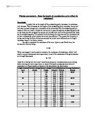
I have decided to use 2cm, 4cm, 6cm, 8cm, 10cm, 12cm, 14cm lengths for my putty. The experiment will be repeated by putting a different current through the circuit. I will repeat the experiment using different current to show that the resistance will be the same. The currents we will use are 0.1, 0.15, 0.2 0.25, 0.3, 0.35amps. The diameter I will keep constant is 1.5cm
1)connect the circuit together with 14cm length of putty.
2)Start with the current being 0.1A, using the variable resistor and write down the voltage and then work out the resistance using the formula.
3)repeat this with all the different currents.
4)do exactly the same for all the lengths of the putty.
5)once all the resistance have been worked out for all the currents for all the lengths, work out the average current for that length. This is then the resistance for this length of putty.
Preliminary work:
This preliminary work was done before my investigation and it helped my determine what width I should use for the diameter. For this experiment I kept everything constant but changed the width of the diameter. These are the results from my preliminary work.
From my preliminary work I have decided to use 1.5cm for the diameter as this gave me the most accurate results as you can see they were all the same except for one.
Analysis:
My investigation went very well and the results were as expected. You can see from my graphs that my prediction has been proved. On the graph that shows the average resistance of the different lengths of putty at different currents u can see that they are all almost a straight line. This proves that although the current had changed it did not effect the resistance. This graph also shows how that as the lengths increase so does the resistance of the putty. This therefore agrees with my theory and prediction in my plan. The graph titled ‘Physics Investigation’ also shows that as the length of the putty increased as did the resistance. This line is almost straight which shows that the length is proportional to resistance.
I plotted the graphs showing the current and voltage for each length of putty, with all the lengths the line is almost straight diagonally therefore shows that current is proportional to resistance. This proves my theory because if current and voltage were not proportional then the resistance of the putty would change with the current. From these graphs you can work out the resistance as it is the same as the gradient.
On the 12cm graph showing voltage and current you can see that there is a result that is out of place at 0.15A. This may be due to the fact that some carbon may have been rubbed off whilst being rolled into a cylinder, or the temperature may have dropped slightly. I tried to get the diameter exact but this was difficult and therefore the diameter may not have been correct throughout. Apart from that I can see from my graphs that there is no other obvious result that looks wrong.
My investigation proves my theory that the longer the putty is, the more resistance there will be. The electricity took longer to jump through the free moving electrons to go through the putty. Therefore when the putty is shorter the resistance is less as there are less free moving electrons for the electricity to pass through. You can see this is true from all my graphs.
Evaluation:
As my results were accurate and proved my theory there is not much that could be done to improve it. However, I could investigate the resistance of the lengths in between the ones that I did and I should also use some kind of mechanism so that I would know that the diameter was the same throughout the putty. This would make the results more reliable although my results were reliable enough to prove my prediction.
I think that I worked well on my investigation and completed it within the time specified. I worked carefully and safely.
To investigate further in this work I could experiment with temperature or changing another factor. This would be interesting to see how all the factors would effect the resistance of the carbon putty.