RLA-1 = Relay (DPDT) D1 = D2 = 1N4001
Operation
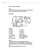
The heart of the circuit is a 555 timer chip configured in astable mode.
This means the out put at pin 3 is constantly changing, i.e. the output goes high (9V) for a specified time and then low (0V) for a specified time before again switching high.
The frequency is controlled by the size of R1, VR1, and C1.
Formula to calculate the frequency:-
From values of R1, VR1, and C1. The frequency of the output is set to 1 hertz
(approximately).
This means the red LED is lit then unlit each half second, also the yellow LED lit then unlit for half second durations.
Lets look at the operation of LEDs.
Consider the output voltage at pin three to be 0V.
With 9V on the top rail, and 0V on pin 3, current can now flow through resistor R2 and the LED, so the red LED is lit.
With the voltage on pin 3 =0V, no current can flow through the yellow LED to ground,
so the yellow LED is unlit.
Now consider what happens when pin 3 goes to 9V (high). With the top rail and pin 3 both
at 9 V, no current can flow through the red LED, so it is unlit, but with 9V on pin 3 and 0V on the bottom rail, current can flow through the yellow LED so it is now lit.
Thus the LEDS flash on and off alternately.
It is most important an LED must not have no more than 2 V dropped across it. Also
the current flowing through it should not exceed 20 mA
When output pin is low (0V), with 9V on the top rail, 7V must be dropped across
a resistor to limit the voltage across the LED to 2V.
With 7V dropped across it, and maximum permissible current of 20 mA flowing through the LED, the size of the resistor can be calculated using Ohms Law:
In electronic circuits it is not good practice to have components operating
at their upper limits, so a resistor value of 390 or 470 ohms should be used.
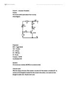
The output from pin 3 is fed via R5 to the base of transistor (TIP121).
The circuit uses a transistor (TIP121) as an electronic switch.
Transistor action.
First it must be explained that transistor (TIP 121) is a special type of transistor. It is in effect two transistors housed in one package. It has the advantage of being able to pass a much heavier current than the ordinary transistor.
When the voltage on the base of the transistor is less than 1.2V, the transistor is switched off, no current can flow through the transistor from collector to emitter, so no current can flow through the relay.
If more than 1.2V is applied to the base, the transistor switches on. Now current can pass easily from collector to emitter, so current can flow from the top rail, through the relay, the transistor, and back to the battery.
When the relay is activated the motor (vibration) is switched on.
Thus as the output from pin 3 (555) goes high and then low alternately, the transistor will
switch on and off, which in turn will activate and deactivate the relay causing the motor to rotate and stop.
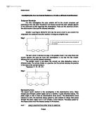
Latching mechanism
The output from the primary alarm system is connected via a diode to the gate of a thyristor. When a positive voltage is applied to the gate the thyristor will switch on and provide a path for the current to return to the battery, so the circuit can now operate.