The maximum voltage that can be used is 5V.
Using Ohm’s law, I can find the maximum resistor value that can be used in the two circuits.
Resistance = Voltage
Current
R = 5
0.001
= 50,000Ω
This value is much higher than the smallest resistor value by 1000 times. These values are therefore the upper and lower limit resistors that I can use in both the circuits to test how the resistance affects the current and the voltage.
What if a 50Ω resistor was placed in circuit 1?
50Ω resistor placed in circuit 2;
I can now see that if I placed a 50Ω resistor in both circuits, circuit 1 would be the best circuit because the resistance measured is nearer 50Ω at 45.95Ω.
What if a 50,000Ω resistor was placed in circuit 1?
What if a 50,000Ω resistor was placed in circuit 2;
I can now see if I placed a 50,000Ω in both circuits, circuit 2 would be the best circuit to use because the resistance measured is nearer 50,000Ω at 50040Ω.
What if I used a 100Ω resistor in circuit 1?
What if I used a 100Ω resistor in circuit 2?
I can now see that if I placed a 100Ω resistor in both circuits, circuit 2 would be the best circuit to use because the resistance measured is nearer 100Ω at 140Ω.
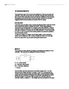
I will need to use the following apparatus to allow me to carry out the two experiments;
An Ammeter – this will allow me to measure the current in amps or milliamps.
A Voltmeter – this will allow me to measure the voltage across a point in a circuit. The voltmeter is measuring the potential difference across two points in the circuit. The potential difference is the energy supplied to each unit of charge; this is how many joules of energy are given up by each coulomb passing through.
There are many different variables I will have to consider for the two circuits I am investigating. Two variables will be the current and voltage from the circuit with the set resistance, these are output variables. The input variable will be the resistance; I have to calculate the resistor values to use in both circuits.
I have to ensure the control variables are kept the same in both of the circuits of the experiment will become unfair. I will have to use the same power supply in each of the circuits because if I used different ones for each circuit, one may have a higher internal resistance than the other. The internal resistance would be a big factor in determining the accuracy of the current and voltage readings I will obtain.
Using the same power supply will eliminate any systematic error that may occur. I will use the same connecting wires to connect all the components in the circuit, this is due to resistance. I will use normal copper wires in the investigation, these will have some resistance but it will be too small to affect my final results.
I will have to use the same voltmeter and ammeter in both circuits because the voltmeter should have a high resistance to allow only a small current to flow and the ammeter should have a low resistance to prevent the voltage changing, therefore changing the current through it. If I changed any of the meters they may have different resistances and this will change the voltage and current readings they measure.
I will keep the resistor holders the same for both circuits, this is due to resistance, if I changed the holders, one may have a slightly higher or lower resistance.
The only variable I am changing throughout the investigation is the resistors. I will be observing the effect that changing the value has on the arrangement of the two circuits.
I have to ensure my investigation is safe. If the power supply was to overheat or a large current was to pass through the wires, a burn would be produced as well as damage to the equipment. To stop this happening I will keep the output EMF below 6 volts, these will be the 6 volts has shown on the voltmeter. Keeping the voltage below 6 volts will make sure that the amount flowing in the circuit is never too large to cause the wires to get hot. The power supply has built in protection to prevent a large current flowing. I will use a voltmeter to take a precise reading of the voltage throughout the circuit, not the power supply. This is because the output EMF that the power supply states cannot be relied on, due to internal resistance of all the components inside it. As the charge flows through the pack, it gains energy “Joules per Coulomb”, which is governed by the voltage across it. There is some resistance that the charge has to overcome; some of this energy gained is then lost overcoming the internal resistance of the power supply. The loss in output voltage is called “the lost volt” and can be calculated using E = IR +r (r is the internal resistance of the power supply).
The colour codes for the resistors I am going to use, these will make it easy to find the resistors;
As you can see I have chosen resistor values that are able to give me a wide range of results, now the ammeter and voltmeter are important, because these are the devices that will give me the readings that I am basing my experiment on. If any of the meters is slightly inaccurate this could cause my results obtained to be inaccurate. The meters a am using are analogue in the way in which they measure current and voltage, they use the electromagnetic effect of a charge interacting in a magnetic field to produce movement. This movement swings a pointer on a scale to measure the voltage or current, depending on the meter used.
Results
Graphs
Graph 1
The graph below is to show how the resistances increase as the value of the resistor increases in both circuits.
Graph 2
Graph to show Resistor Values against R1/R2 ratio.
Conclusion
From my results I can see that circuit 1 isn’t very accurate, I think this may be due to the position of the voltmeter. In circuit 1, the voltmeter is taking the potential difference across the resistor only and not the ammeter; the ammeter has its own internal resistance of 40 ohms. With the ammeter having its own internal resistance, energy is required to make charge flow through the ammeter and then through the resistor. Energy is required to push the charge through the resistor but this energy is lost when it is passing through the ammeter and the voltage drops. This explains why the resistances calculated in circuit 1 are so low.
In circuit 2, the potential difference is being measured across both the resistor and ammeter. The internal resistance of the ammeter is now been taken into consideration. The calculation of the resistor value is more accurate now the ammeter is been taken into consideration.
Both circuits produce different results. Circuit 1 is very in accurate. Circuit 2, however, is a much better circuit to use, as the results calculated are much nearer the resistor values.
I can see that when I plotted graph 1, the line for circuit 2 carries on increasing as the resistor value increases, but the line for circuit 1 does not increase like that of circuit 2 because the resistance that is measured is no where near that of the resistor value. Until the resistor value of 22000, the line of the graph for both circuits follows a very similar pattern. Then has I increase the resistor value to 22000 the line for circuit 2 increase as I expect it 2 but the line for circuit 1, increases but not has I expected, the given resistance is only 15277.78 this is 6722.22 ohms lower than the given resistor value and this carries on always through the investigation. This is because in circuit 1 the ammeter has its own internal resistance of 40 ohms and in this circuit the voltmeter is only measuring the potential difference across the resistor and not taking into account the potential difference of the ammeter.
The ratios show how the two-resistor values change, with the number gradually getting smaller, has there is a bigger difference from the resistance measured in circuit 2 and that of circuit 1.
Evaluation
Internal resistance of both the ammeter and voltmeter could have affected my readings. The power supply has wires that have a resistance of their own and this fact did not get taken into account when the voltage and current readings are taken. The power supply would only have a tiny internal resistance but it still may make the results less accurate than they could be.
The fact that the connecting wires have some resistance plays a part in the results obtained, even though the wires have only a very small resistance it could make the results less accurate.
Repeating the experiment twice was not sufficient enough, if I had repeated the experiment 5 times this would have given me a much more precise average.
The accuracy of the ammeter and voltmeter is a determining factor in obtaining accurate results. If they are slightly inaccurate this could make my results accurate. I do not think that anything was wrong with the accuracy of the ammeter and voltmeter. Using digital meters would be a better idea has the scales are extremely accurate and the correct resistance could be used, such as very high resistance for the voltmeter to reduce the current the current flowing through it. Parallax errors could have affected my results, as it is difficult to judge whether the meters needle is on one line or the other, depending on which angle you look at the meter. A digital meter would stop this error as it gives a reading in exact numbers.
If I was to repeat the experiment again, I would like to use digital meters to record the current and voltage because this would ensure that my results would be as accurate as they possibly could be. I would leave the power supply on for as little time as possible to stop the resistors heating up as I fink this increases their values.
I think my investigation did prove what I was trying to prove, what I discovered matched my prediction and circuit 2 was the best circuit to use.
Kirsty Marie Hatfield New College, Pontefract