I will measure the length to the length of the worktop so the length is maximised. Adding each weight gradually, having recordings for each weight 3 times therefore diving the error by three.
Voltmeter and Ammeter flickers therefore less accurate. Therefore more likely to obtain anomalous results. Resistance in leads cause possible errors as less accurate measurements of voltage and current.
Small weights allow weight to be changed and maximum weight can be lifted and can obtain ten results. Strong string, but light and does not get stretched; check the size of string before and after the experiment, so we can see any extension. Thin, so does not overlap on the rotating winch. Averages of recording will help improve accuracy.
Plot a graph to show anomalies on a best fit, should show errors or a pattern. Weights might not be accurate weigh them to see if the weight is exact or not. the scales could also be inaccurate therefore hard to make it certain that there is less chance of error.
AS Level Experiment Hermanjit Virk 12WSI
Electric Motor Efficiency Coursework
Observation and Results
Results:
See graphs.
AS Level Experiment Hermanjit Virk 12WSI
Electric Motor Efficiency Coursework
Interpretation and Evaluation
Conclusion: As you can see from my results my prediction was correct, as you increase the weight on the motor it will have to do more work. As the voltage and current remained constant the efficiency became higher with the more weights that were placed on to the string to be lifted. Due to fact that the motor had to do more work, the time increased resulting in a positive gradient through my graph. Obviously the time was not as accurate as I would have hoped as the motor picked little weights quickly over short distances.
The efficiency for the motor in this experiment was quite low, so not much of the energy put in was used usefully. The highest efficiency reached in my results was when picking up the top weight of 1N, which my calculations showed to have the efficiency of 14.04%, this means that 86.06% was wasted energy; this was probably due to the friction of moving parts in the motor resulting in heat and sound released into the environment.
Evaluation: My experiment went reasonably well, I repeated my results three times this increased the amount of accuracy in the experiment, it helped divide error in time by three. I followed my plan making sure of safety and went through my method before conducting the experiment. The biggest error in the experiment as I have previously discussed was time, so it was unlikely that any one could have had results that were perfect.
Other errors in my experiment were caused by practical faults, or by a more technical reason. The voltmeter and ammeter persistently changed value in the experiment; therefore we can tell that maybe some resistance was carried in the connecting leads.
If I was to test again, I would change the timing technique by using a light gate instrument. To use the light gate instrument I would place the weight at the start when it starts to moving towards the motor it will pass a sensitive sensor that then turn the time of through some kind force mechanism. This could divide the human error by about ten.
If I could repeat the test I would test the affect of voltage on the efficiency, and I would use one set number of weights. This test would probably show us a decrease in efficiency as the voltage is increased.
AS Level Experiment Hermanjit Virk 12WSI
Lens Coursework
Plan
Aim: In this investigation, I will be changing the factors of object distance and image distance, to find the focal length of a converging lens.
Apparatus: Converging Lens (2, plus combination of both)
Blue – Tack
Light Box
Lens Stand
Power Supply
Ruler
Screen
Tape (Scissors)
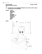
Diagram:
Safety: In this experiment it is important to consider the safety aspects when carrying out this practical task; I will make sure of the following things before starting the experiment:
- Equipment correctly setup (Above diagram), avoiding confusion, less chance of accidents.
- Make sure that the leads from light box are working in order
- The Power supply is working, and the voltage is not exceeding the limit
- Check the circuit before starting and be standing during the experiment
- Lens should be affixed firmly with blue tack to the Lens stand, no chance of breaking
- Light box working and in order, light should be bright and clear
- Do not look directly into the bright light, where safety goggles
- Work top should be cleared of any objects which are not being used in the experiment
- Apparatus should be spread out neatly and spaciously
Variables:
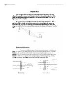
Theory: In this experiment we will be using converging lenses, any lens that is fatter at the centre than at its edges will converge. (Below) We can see a parallel beam converging through a point, F known as the principle focus of the lens.
The distance from the lens to this point is called the focal length, f, of the lens. The power of a lens, P (the unit for the power of a lens is dioptre, D), can also be measured, which is the reciprocal of the focal length in metres:
P = 1/f
When a lens converges light, it carries with it an image of the source object correct in every detail. This can then be projected on to a screen, this is a real image. To get the clearest image the object distance (u), and image distance (v), must be exactly proportional to the focal length (f), (Previous diagram). The equation connecting the distance of an object from the lens and the distance for its image is:
1/f = 1/u + 1/v
The focal length of converging lenses are positive, therefore the images produced are of real objects and images not virtual which can be produced by diverging lenses.
Material of the lenses is a factor in this experiment but as I will be using glass it is important to know what effect this has on the lens and image. The material of the lens will not be changing. Glass is a clear transparent material and that is one of the reasons it is being used. Glass is harder than plastic therefore it does not scratch easily and it can then help produce a clear image. The material does not easily deform therefore the focal point can remain constant.
Glass is good at transmitting light; it absorbs very little. The problem however is that glass reflects a proportion of the light. It reflects about 10% of the light this can be reduced by adding a anti-reflection coating to the lens. This increases the transmission of light up to 99% making the image brighter.
Prediction: The fatter in the middle, out of the two lenses that I decide to use, the smaller the focal length. Therefore if one of the lenses is twice as fat in the middle compared to the other. Its focal length will be twice as short, because it will refract light at a doubly greater angle. Therefore I will be able to have a larger range of results with a fatter lens as image will appear earlier and take longer to fully deform. Therefore when both lenses are combined the focal length will obviously be smaller than that of both lenses in proportion.
When I increase the size of the object distance (u, to then obtain a clearer picture I will probably have to decrease the size of v by a proportional amount if I would like to attain a clear picture. Therefore if I double the distance of object distance (u), I will have to therefore decrease the image distance by a proportional extent, to acquire a fine focus of the image. Therefore as I increase the length of both object distance (u) and the image distance (v), the picture will gradually become more distorted until it is no longer a real image.
It is important that both the lenses are the same material if I want to obtain a good set of results. Both lenses should be transparent and have minimal scratches to prevent image being unclear. The lens must also be hard so it does not easily get affected in any form during the experiment, so there is less chance of the results being anomalous. Both lenses should not be deformed in shape or any other way, as this could affect the focal point from remaining constant.
Method: In this practical I am going to change the object distance (u) and the image distance (v), to two different converging lenses. I will do this by planning out how I will conduct the experiment:
- Clear the work top
- Setup the power supply and connect the ray box
- Blue – Tack the metre rule to the work top, making sure it is secure
- Set the lens stand in front of the ray box
- Setup the screen in front of the lens stand
- Calculate the focal length of the lens, by using parallel light from a window
- Blue – Tack the lens into the lens stand making sure it is secure
- Switch on the power supply and gradually maximise the voltage
- Stick tape on to side of ray box, lens and screen from were I will measure from and to
- Using a setsquare measure the middle of the lens and check that all equipment is set out parallel, avoiding errors in measurements
- Vary distance of object distance(u) and image distance (v) until I get a large range of well spaced results, I will repeat my readings so that I can obtain an average
- Increase the lengths of both object distance(u) and image distance (v) until there is no longer a real image, increasing the length by 0.5 – 2.0 cm each time
- Record my results in a table, It should be clear and informative, it should state any units
- Plot my results onto a graph
- The table will have ten results for both lenses, and the combination of both lenses, having a column for object distance (u), image distance (v), and the calculation of focal length (f), using the equation:
1/f = 1/u + 1/v
My results table will look similar to the following:
Sensitivity: In this experiment it is important that I am aware of errors; I can decrease the amount of inaccuracies by checking the sensitivity of my practical when measuring and recording:
To measure the lengths of object distance (u) and image distance (v), I will be using a metre rule and slowly increasing the lengths of both. The error in reading from a metre ruler in each reading is +/-0.5mm therefore the error in accuracy is +/-1mm.
The error of a metre rule can be overcome and decreased by using a vernier callipers which would help divide the error by ten times, the error being +/-0.1mm. If more accuracy was needed a micrometer could be used which in fact is ten times more accurate then a vernier.
It will also be important to make sure that the ruler is straight as well as any other equipment when measuring, and not at an angle. This could cause an error in the distance being measured. To overcome this I may use a setsquare to line up the equipment. With a ruler I might decide to place, it directly parallel to the end of the bench, and blue – tack it firmly down. I could also use the setsquare to measure the middle of the lens so it is clear to see where I am measuring from.
I will take a range of ten readings and make an average of three results for each reading therefore improving my results dividing the error by three. This then gives more accurate table of results.
Errors could also happen if the lenses are scratched, if one is scratched more than the other it will therefore transmit less light and cause errors in my results. That is why it will be important to pick lenses that are similar in shape and only different in size.
AS Level Experiment Hermanjit Virk 12WSI
Lens Coursework
Observation and Results
Results:
See graphs.
AS Level Experiment Hermanjit Virk 12WSI
Lens Coursework
Interpretation and Evaluation
Conclusion: As we can see from my results the fatter in the middle, out of the two lenses that I decided to use, the smaller the focal length. This is because the lens refracts light at a greater angle. Therefore I will have a large range of results with a fatter lens as image will appeared earlier and took longer to fully deform. Therefore when both lenses were combined the focal length was being smaller than that of both lenses in proportion, as I had earlier predicted.
When I increased the size of the object distance (u), to obtain a clear picture, I had to decrease the size of v by a proportional amount. Therefore when I increased the length of both object distance (u) and the image distance (v), the picture gradually became more distorted until it was no longer a real image.
It was important that both the lenses were the same material as I wanted to obtain a good set of results. Both lenses were transparent and had minimal scratches to prevent image being unclear. The lens was also hard so it did not easily get affected in any form during the experiment, so there was less chance of the results being anomalous. Both lenses were not deformed in shape or any other way, the glass material was not deformed so it did not affect the focal point from remaining constant.
Evaluation: I could have done the experiment differently by measuring the distances more accurately, for example the focal length as then I could have see how accurate my results were. To have done this I might have used a vernier calliper, which could have helped divided errors by ten times.
I could have also have improved my experiment by checking the measuring points more carefully and this would have made the difference in accuracy. Using a setsquare to measure the middle of the lens was not as accurate as I would have hoped as the stand was where I eventually measured from because the ruler was in a fixed position.
I also had anomalies as combining lenses probably was not that accurate as the glass was still separate from each other and maybe the results were inaccurate due to this. It was hard to choose the position to measure the light from as it was hard to be accurate in choosing where the light started as the bulb was covered from the sides as it was in a ray box.
In think if I was to do this experiment over I would use a larger range in the lenses as it would have given me a better range of results, and when combining the lenses using something to hold them tight. I would have also spent more time in using a different measurements if the lenses could have produced a larger range of results.