- Field
It is easily found that
- Number of Turns
It is clear that
- Area
It is also true that
- Orientation of Coil and Field
The relation of induced e.m.f. and the orientation of coil and field is as follows:
EXPERIMENTS
Fig. 1
At first, a square solenoid is connected to a signal generator via an a.c. ammeter. 10 turns of wire are coiled around the solenoid and the wire is connected to a CRO.
At the beginning of the experiment, the frequency of signal generator is set at 500Hz. The current is set at 860mA. The smaller square solenoid is used. l is the peak-to-peak reading in C.R.O.
The frequency is changed to investigate its effect on induced e.m.f. The current is kept constant every time whenever the frequency is changed.
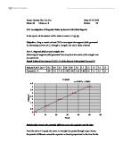
Investigation 1: Rate of Change
Results:
The graph of l against f is drawn on a separate graph paper (GRAPH 1).
Measurements:
From the graph, it can be said that the relation between l and f is linear. Although several points are quite far from the lines, three of the points can be connected firmly in a straight line.
Then the frequency is reset to 500Hz. The smaller square solenoid is used.
The current supply is changed this time to investigate its effect on induced e.m.f.
Investigation 2: Field
Results:
The graph of l against I is drawn on a separate graph paper.
Measurements:
From the graph, it is easily observed that the relation between l and I is linear as the points nearly lie in a straight line (GRAPH 2).
Then the frequency is kept at 500Hz. The smaller square solenoid is used. The current is also kept constant at 860mA. This time, the number of turns of the wire round the solenoid is changed to investigate its effect on induced e.m.f.
Investigation 3: Number of Turns
Results:
The graph of l against N is drawn on a separate graph paper.
Measurements:
From the graph, it is easily observed that the relation between l and N is linear as all the points fall in a straight line (GRAPH 3).
Then the two square solenoids with different sizes are connected in series to the signal generator set a 1kHz. The two solenoids have the same number of turns of 10 of wire around them. The frequency and the current remain unchanged. One coil is connected to channel 1 and the other to channel 2 of the C.R.O.
The effect of the cross-sectional area of the coils on induced e.m.f. is observed.
Investigation 4: Area
Results:
Smaller solenoid used: l = 1.2 cm
Large solenoid used: l = 2.8 cm
It is found that with a larger cross-sectional area of the coils, the induced e.m.f. is larger.
Next, we have another setup to investigate the effect of orientation of coil and field on the induced e.m.f.
The diagram below (Fig. 2) shows the setup. A 10-turn flat coil is wound on a magnetic field board and it is connected to a signal generator set at 1kHz.
* The signal generator is set at 10 x 100Hz instead of 1 x 1kHz because it is found that the latter
setting is not 1kHz as seen on the C.R.O. screen.
Fig. 2
An axial search coil to a C.R.O. and it is placed vertically at the centre of the coil.
The search coil is then titled and the change in the length of the vertical trace on the C.R.O. is recorded.
Investigation 5: Orientation of Coil and Field
Results:
When the axial search coil placed vertically at the centre of the coil, l = 7.2 cm
At half of the length of the vertical trace on the C.R.O., i.e. l = 3.6cm, it is found that
The vertical length of the coil, h = 11.5 cm
The length of the axial search coil, s = 20 cm
The angle through which the axis of the search coil is as follows:
With the decrease of the angle, the vertical trace on the C.R.O. is also decreased.
CONCLUSIONS
The induced e.m.f can be affected in five ways.
Through the investigations, it can be concluded that the induced e.m.f. is directly proportional to
-
the changing magnetic field in a neighbouring coil and rate of change of magnetic field (frequency of A.C. supply, f ),
-
magnetic field strength (current through the solenoid, B), and
-
number of turns of coil N.
Theoretically, it is also directly proportional to
-
the induced e.m.f. is increased with increasing area of surface of solenoid A, and
-
the angle through which the axis of the search coil ().
But whether or not it is proportional to A is not verified because the cross-sectional area of the coils has not been measured.
In addition, the effect of orientation of coil and field on induced e.m.f. found ( is not as what is predicted (. However, it is still roughly found that the induced e.m.f. has been decreased with decreasing angle.
DISCUSSIONS
Question
In investigating the relationship between the induced e.m.f. and area of coil, the two solenoids have same magnetic field. As in the equation for flux density near the centre of the solenoid
where is the permeability of free space, I is the current and n is the number of turns of coil.
As B is not related to the area of the solenoid, the two solenoids have same magnetic field.
One possible method to test it is by making use of the search coil (Fig. 3).
The search coil is connected to the Y-plate of C.R.O. with the time base off. It is placed next to onf of the solenoids and rotated until the C.R.O. reading reaches maximum. Then the peak-to-peak length is measured. The procedures are repeated and hence the result can be found.
If an alternating field passes through the coil, an e.m.f. is induced and measured by the C.R.O. The length of the vertical trace is proportional to the maximum value of the alternating flux density.
Fig. 3
Precautions
1. Increase the alternating current gently from zero. Otherwise, the a.c. ammeter would be over-deflected which may cause damage to the ammeter.
2. The ends of PVC covered copper wire should be twisted and kept as far away from the solenoid as possible. Otherwise, there may be induced e.m.f. induced by that part of the copper wire which may affect the result obtained by a using a desired number of turns of coil.
3. In every investigation, there should be only one unique changing factor that affects the result. For example, in investigating the relationship between induced e.m.f. and frequency, only the frequency should be varied. In other words, the other parameters should be kept constant. Otherwise, the result would not be what we could expect and the result should not be accepted.
Sources of errors
1. The frequency of A.C. generated by the signal generator might not be correct. When the experiment was carried out, it was found that 10 x 100Hz was very different from 1 x 1kHz as seen on the C.R.O. screen where the latter one had a high level of inaccuracy. It had been assumed that the frequency indicated on the signal generator was correct. However, this might not be a significant source of error in finding out just the relationship between induced e.m.f. and frequency since the induced e.m.f. could still increase with increasing frequency.
2. The ends of the wires around the solenoid could induce e.m.f. However, this seems not to be a significant source of error because the effect is quite small unless the ends of the wires are put around the solenoid.
3. The axial search coil should be put in the centre of the 10-turn coil. Otherwise, the result obtain would not be the maximum value which may affect the angle through which the axis of the search coil.
Possible Improvements
- Measure the frequency generated by the signal generator each time when the effect of varying frequency on induced e.m.f. is observed to ensure the signal generator gives out desired frequency.
- Place the search coil as near in the centre of the 10-turn coil as possible to reduce the error.