-
All qualitative results were recoded in Table 1.
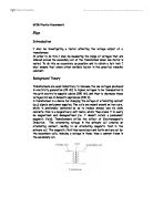
DIAGRAM 1: Set up for Experiment 1.
RESULTS: Table 1-Qualitative Observations of Experiment 1.
ANALYSIS and DISCUSSION:
It is necessary to note that the galvanometer reading measures the current induced through the solenoid. The equation V = IR shows that I ά V and thus the galvanometer may also gives an indication of induced emf.
STEPS 2A, B and C as well as 3A and B:
These results show that relative motion is needed between the solenoid and the magnet. Notice that the galvanometer displayed a positive reading when the magnet was plunged into the solenoid as well as when the solenoid was thrust upwards onto the stationary magnet. The results suggest that it matters not which piece is moved, as long as there is relative motion.
When the magnet was moved in a circular path or when the solenoid was moved left, the galvanometer displayed zero. These results suggest that relative movement must occur at right angles to the plain of the solenoid, rather than the plane of the solenoid.
When the magnet was held inside the solenoid no reading was observed. This can be interpreted as a need for continuous motion between the two objects. It is not enough that there the magnet is within the solenoid; there must be motion in one of the two objects perpendicular to the plane of the solenoid.
STEPS 4A and B:
When the iron core was placed within the solenoid an increase in both positive and negative readings was observed. Therefore the results indicate that the iron core increases the resulting current induced by the relative perpendicular motion of solenoid and magnet.
STEPS 5A, B and C:
When the magnet’s perpendicular velocity was increased from slow to fast the reading on the galvanometer scale increased in a similar fashion. These results suggest that velocity is proportional to the resulting current induced by the relative perpendicular motion of solenoid and magnet.
It is important to identify the relationship between velocity and area. When either the magnet or solenoid has velocity the area of conductor (solenoid) cut by the magnetic field lines of the magnet changes.
According to this the following relationship is suggested by the results.
STEPS 6A:
As the number of magnets used increased, the magnetism present in the experiment was increased and a resultant increased current was observed. Therefore a relationship between magnetism and current has been established with induced current increasing as the strength of magnet (and thus magnetic field) increases. Thus the following relationship is suggested by the results.
STEPS 7A:
As the number of turns present in the solenoid increased so too did the induced current present through the galvanometer. This once again suggests a proportional relationship between the turns in a solenoid and current induced in the solenoid. Thus the following relationship is suggested by the results.
CONCLUSIONS:
In conclusion, the results of this experiment support Faraday’s Law of Electromagnetic Induction which states that:
Whenever the magnetic field in the region of a conductor changes, an electric potential rise (emf) is induced across the conductor. If a circuit is provided, then an electric current will flow through the circuit. The emf induced in a loop is directly proportional to the rate at which the flux through that loop changes with time.
The results qualitatively concur with Faraday’s law in that a current was induced when the above conditions were met. As well as concurring with the qualitative demands of Faraday’s Law, the results also support the quantitative section of the law; the equation “emf = NA∆B / ∆t.”
The results show proportional relationships between:
- induced current and velocity
- induced current and magnetic flux density
- induced current and number of turns on a solenoid.
These three relationships can be derived from Faraday’s initial equation and thus support his findings.
The results also suggest that the presence of an iron core within the solenoid increases the current induced and thus the emf.