With the decrease of area of overlap, the capacitance is also decreased. Hence, the number of charges stored is also decreased.
- Relative permittivity
It is known that by putting a dielectric between the plates could increase the capacitance. A dielectric is a material that can be polarized by an electric field. When a dielectric material is placed in a uniform electric field, one surface will contain many positive ends of molecules and the other surface will contain many negative ends. When a dielectric is placed between charged plates, the polarization of the medium produces an electric field opposing the field of the charges on the plate.
As the capacitance is inversely proportional to the electric field between the plates, the presence of the dielectric reduces the effective electric field, he capacitance of the parallel plate is increased. The permittivity is a characteristic of space, and the relative permittivity of free space. Therefore the capacitance of a capacitor with a dielectric is given by
Procedure
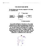
The circuit was set up as shown below.
The capacitor plates were separated with 4 polythene spacers placed at the corners. The frequency and voltage of the signal generator was adjusted such that a sound was heard and the spot on the light beam galvanometer was deflected.
Investigation 1 : Charge and Applied Potential Difference
We separate the capacitor plates with 4 polythene spacers, one at each corner. We then investigate the change of current with the change of voltage which is being done by connecting more cells.
Results:
Signal frequency f = 400Hz
Galvanometer sensitivity k = 20mm/µA
From the graph, it is easily observed that the relation between I and V is linear as the points nearly lie in a straight line.
Investigation 2 : Effect of Plate Separation
We investigate the effect of plate separation by putting more spacers. We connect the parallel-plate capacitor to 6 batteries, i.e. 9V and this is unchanged during the whole investigation.
Investigation 3 : Effect of Area of Overlap
We investigate the effect of area of overlap by decreasing the overlapping area between the two plates. We connect the parallel-plate capacitor to 6 batteries, i.e 9V and 1 spacer to separate them. These two are unchanged during the whole investigation.
Investigation 4 : Effect of Dielectric
It is known that, by putting a dielectric inside the parallel capacitor, the capacitance will be larger. We can find the relative permittivity of a dielectric, which is compared with the permittivity in vacuum. The two plates are fully overlapped. We compare the difference on the deflection without a dielectric and with a dielectric.
Discussion
Having done the series of experiments, we can conclude that there are some factors affecting the capacitance of a parallel-plate capacitor. These factors include plate separation, area of overlap and the existence of a dielectric.
We have measured that the value of the capacitance of the capacitor to be
9.2 x 0.1 x F and the relative permittivity of polythene is . It is predicted that the I- and -graph is a straight line. In the experiment, the variation of I with and with was consistent with a straight line within the present limits of uncertainty.
In this experiment, there are plenty of errors. First, there may be stray capacitance from the bench and the wall. As from the I- and -graph that it does not pass through the origin, stray capacitance actually exists. Some field lines from or to the plates may actually come from or go to earth and other circuit component, such as connecting wire. We may say that one plate and earth or another conductor form an extra capacitor. In fact, any two materials can form a capacitor which can store charges. Hence, it’s a major source of errors.
It is assumed that edge effect of the plates can ignored and all field lines between the plates are straight. In fact, the field lines curve at the edges. However, this error may not be significant as the separation between the plates is much smaller than the linear dimensions of the plates.
In addition, the resistor may be too large so that the capacitor is not fully discharged. This will affect the calculated capacitance of the parallel=plate capacitor. This can be significant error if it is not controlled well. Also, there are reading errors.
Furthermore, the frequency generated by the signal generator has not been actually measured. This can affect the obtained capacitance of the parallel-plate capacitor.
However, this error may only affect the investigation between charge and applied p.d. as the other investigations are carried out by using same frequency. It does not affect the other observation.
Added to all these, the height of each spacer is different, hence the separation of the plates is not equal. Therefore the graph of I- is affected.
In order to minimize the above errors, it is suggested to keep the parallel-plate capacitor away as far as possible to avoid stray capacitance. Also, try to measure the frequency using a CRO so that the exact frequency can be measured. Hence, a more accurate result of the capacitance can be measured. Moreover, try to monitor the p.d. across the capacitor with a CRO. Adjust the resistance to a value that the capacitor can be fully discharged and that the light-beam galvanometer cannot be damaged.