Investigation into the elasticity of a set of springs under differing conditions.
Investigation into the elasticity of a set of springs under differing conditions.
Preliminary investigations.
The object of this investigation is to discover how springs react to differing situations. I plan to implement several strategies to discover this. I plan on beginning by ensuring that each of the springs are as similar as is possible, I plan to do this by checking that each of the springs are the same length and that they have the same no. of coils.
I will conduct the experiment as scientifically as possible; this will be done with the use of accurate tools and the careful tabulation of the results.
I will be taking into account the:
Variation in the extension of the spring.
How the springs are affected with the changing of weights.
How the springs are affected when the way in which they are placed is changed i.e. in parallel, series and also when they are on their own.
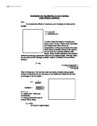
Another product of this experiment will be the proving of Hookes law:
K = F / X
Spring Stiffness = Force / Extension
T = 2 mass
K x g
(Spring Stiffness is also measured by the gradient of the graph)
Where :
T = Periodic Time (s)
K = Spring stiffness
G = Acceleration due to gravity (m/s)
This means that K is the spring stiffness (or spring constant), F is the weight or force applied to the spring and X is the extension of the spring after the force has been applied.
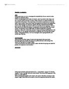
Graphically:
B
Extension (x)
A
Load (F)
This is the graph that I expect to find from my results as it means that the extension of the spring will increase proportionally to the force that is applied to it. The graph should also curve at the top as this will be the elastic limit and will be unable to return to its original position and shape.
The definition of Hookes law is as follows:
An object obeys Hookes Law if the extension produced in it is proportional to the load.
I expect that the spring stiffness (k) will change depending on the arrangements of the springs i.e. in parallel or in series. For example when the springs are in series the spring stiffness should halve and when two springs are in parallel then the spring stiffness will double. This is because when the force is kept at a constant and the extension decreases then the stiffness increases. I believe that this will happen because when the springs are in parallel the resistance to the load will be doubled, thereby halving the extension. I also believe that when the springs are arranged in series then the extension will double, this is because the springs resistance to the load will be halved i.e. decreasing the spring stiffness.
Planning.
I have decided to explore the effect that weights have on a series of springs depending on their combination i.e. in parallel, series etc.
I have also decided to explore the effect that a series of loads has on the oscillations of springs, the springs will be arranged differently so that I may discover how the arrangement affects the oscillations.
For this experiment I will require the following instruments.
* A clamp stand
* A set of up to 5 springs (3 for the experiment and 2 spare in ...
This is a preview of the whole essay
Planning.
I have decided to explore the effect that weights have on a series of springs depending on their combination i.e. in parallel, series etc.
I have also decided to explore the effect that a series of loads has on the oscillations of springs, the springs will be arranged differently so that I may discover how the arrangement affects the oscillations.
For this experiment I will require the following instruments.
* A clamp stand
* A set of up to 5 springs (3 for the experiment and 2 spare in case of accidents)
* A metre rule.
* A thin, long block of wood.
* Sellotape.
* A marker.
* Cardboard
The clamp stand will be used to hold the springs when the experiment is in progress. The springs will be attached to the clamp stand and will be measured at that point using the meter rule. A pointer (made from the card board) will be attached to the meter rule and this will be used as a point of reference whilst measuring the extension. Now I will add a 10N weight onto the spring and wait for the spring to stop oscillating, I will then measure the distance between the marker and the new position. I will repeat this process three times and if necessary a fourth time. The results will be tabulated and kept secure. Once the results for the first weight have been collected I will add another 1N weight, this will continue until there are 5N's on the spring. I have decided not to exceed 5N as it may damage the spring.
If possible I will try to ensure that the spring used will be kept the same. I plan on keeping the experiment fair by ensuring that the equipment used will be constant.
The clamp stand is necessary because it is a stable [piece of equipment that will not move when the experiment being carried out, this also means that it will not affect the results in any way.
The springs that I will be using will need to be as similar as possible because I need them to create as similar results as is possible e.g. if one spring has more coils than another does, then I expect that it will stretch more.
A metre rule is acceptable for this experiment, even though a vernier scale would be more suitable and produce more accurate results.
The loads will each \be weighed before hand to ensure that they are the same force. This is important because my results may become inaccurate due to the wrong weights being added.
I will also weigh the hanger from which the weights will be suspended, this will be taken into consideration throughout.
The second half of the experiment will require a stop clock. I will arrange the springs in a similar fashion as to the way described above. The difference will be that I will be measuring the oscillations of the springs. This will be done by releasing the load when the springs have been extended by 20cm, this will provide a good indicator as the springs are all within their elastic limit and thew will not force the loads to 'bounce' when they reach the top of the oscillation. I hope that this will provide a good set of results that will provide conclusive results.
The experiment will be laid out as follows:
Clamp Stand Metre Rule
Spring
Load (weight)
Desk
Spring
Marker
I believe that this set up will provide the most accurate results and will also be the most efficient tactic to maintain consistency in the results. I will ensure that the distance between the top of the clamp stand and the ground will be kept at a maximum, this is because I do not want the spring or the load to hit the ground whilst the experiment is being conducted.
Safety and Precautions.
I will ensure that the experiment is completed safely by ensuring that all of the loads are safely secured onto the clamp stand. I also plan on ensuring that the springs are placed onto the clamp stand and do not snap, I hope to do this by not placing too many loads onto them, they are dangerous as they are very unreliable and may break if extended too much.
Ensuring correct results are gained.
I will also ensure that all weights are the correct weight, this is important as they may be the wrong weight. This will affect the results as the springs may be extended too much or not enough.
To make the readings as accurate as possible I will add a piece of plastic or straw to the bottom of the weights, this will be used as a pointer to the metre rule.
Once the experiment has been completed and the results have been tabulated then I will take into consideration the errors. This will include any errors in:
. Time keeping i.e stop clock, human reflexes.
2. Measurements i.e the ruler.
Analysis
The results that I have collected have proved very conclusive. From the graphs that have been plotted I have been able to deduce that when the a spring is added to the spring in series then the extension increases proportionally, as is proved below:
Spring
2 Springs
N
2.5
5.1
2N
6.8
3.7
3N
1.1
22.2
4N
5.5
30.5
5N
9.4
38.7
When the load 1N is added to the springs in series the extension is 5.1 cm, however when the load is added to the spring on it's own the extension is only 2.5 cm.
This proves that the equation k = f / x is true. This is because when the load is kept the same but the spring stiffness is doubled then the extension is also doubled.
To work out the spring constant I will need to use the equation:
K = Force or Load / gradient
The spring stiffness is a measure as to how much the string is extended when a load is placed on it. This can be worked out using the equation:
K = F / X
The graph that has been plotted (spring stiffness against load) shows that the stiffness of the spring halves when there are two in series but when two are put in parallel then the stiffness is doubled. However, when there is a spring in series added to two springs in parallel then the stiffness decreases by a quarter. I have also noticed that the spring stiffness remains the same regardless of the load that is being put onto it. This seems to be a defining characteristic of the springs. The only time that the spring stiffness alters noticeably is when the first load is added. This can be attributed to the fact that the springs need to be stretched before hand. This is because they do not stretch, as they should originally, it requires energy to begin stretching away from the coil. This is demonstrated I n the table below where the springs extension alters noticeably.
For example,
Load (N)
Spring
2 Springs in Series
0.39
0.2
2
0.3
0.15
3
0.27
0.14
4
0.26
0.13
5
0.26
0.13
This table shows that when the springs are in parallel then the spring stiffness halves, this as I had believed in my planning. I have also noticed that the spring stiffness does not change much regardless of the load, I did not take this factor into consideration during my planning and prediction.
From the graph I have also noticed that the springs in parallel have a spring stiffness almost exactly four times greater than the springs in series. This is because the springs in series have a lower spring stiffness than when they are in parallel, I believe that this is because there is a larger number of coils working together to hold the force when the springs are in parallel. When in series the coils spread further so that the force of the weight is spread out evenly.
The second experiment also proved to be extremely informative, the results were very conclusive and complied with my predictions. The results below help to prove my prediction that the time for one oscillation will increase or decrease uniformly depending on the arrangement of the springs.
The Results
Spring
2 Springs
3 Springs
2 Springs Parallel
Time Taken (s)
21.2
29.8
36.4
5.5
Time Taken (s)
20.7
30.1
36.2
5.3
Average
20.9
29.9
36.3
5.4
Periodic Time
2.1
3.0
3.6
.5
Predicted Time
2.1
2.9
unknown
.36
The results gained from the experiment are the ones that I expected, as shown in the table. This helps to prove Hookes law, because the equation for calculating the correct periodic times works. The differences between the actual results and the calculated times can be attributed to errors by people or inaccuracies in the equipment. It is also very difficult to judge when each individual oscillation has been completed.
As stated above the results testify to my prediction In that the periodic time for one oscillation changes depending on the arrangements of the springs. For example when there is a single spring the periodic time is 2.1s, however when there are 2 springs in parallel then the periodic time is 1.5s. these are not the results that I expected exactly but they do follow the trend that I expected. I believed that the periodic time would be halved when the springs are in parallel.
For future reference.
If I was to conduct the experiment I would make a few changes, for example I would have liked to have used more accurate equipment i.e.:
* A vernier scale.
* A more advanced stop clock (possibly motion sensitive).
* Better springs.
I have also recognised that there are many errors in the experiment, most are based on human error but some are due to inaccuracies in the equipment.
. Human Errors.
* Timing - there are errors in the timing as peoples reaction times are at best 0.2 seconds. This means that the times could be inaccurate.
* Counting the Oscillations - errors can be made when counting oscillations as your attention may be diverted.
2. Mechanical Errors.
* Weight/Force - the weights used may have been inaccurate.
* Springs - each oscillation would not have been the same as the rest as a result of the individual springs. The oscillation may have been larger or smaller.
* Ruler - the rulers are accurate to the nearest millimeter, there may be errors when calculating the precise extension.
Over all the experiment was a success apart from the occasional error described above. The results proved conclusive and have conformed to my predictions. The extension of the spring did halve when the springs were changed from single in series to two in parallel etc. the graphs can be used to help prove hookes laws and also to derive them.
The changes that could have been made are minimal and may not have affected the results greatly.