Where y= lnI, x= t, gradient = and lastly y- intercept = lnImax
-
Resistance(R) of uncertainty ±2% is measured using the multi-meter and the Capacitance (C) is found by using the gradient = ∴
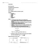
Diagrams: Showing setup of circuits in question.
Results:
Resistance (R)= 99.2 kΩ
± D (T) Average = 0.84s or 1.00%
Analysis:
Qualitative Analysis:
-
Circuit 1 (CR), Figure 3.1: When the switch was opened, the reading on the ammeter was 0μA, there was no current. Immediately after the switch was closed, the ammeter read 100μA as the capacitor became charged over a period of time. The reading of the ammeter was then observed to decrease and it started to reduce and a decreasing rate until it got to 60μA after the switch was open and the current was discharged from the capacitor, where it was observed to remain.
-
Circuit 2 (Main CR circuit), Figure 3.2: When the switch was closed the current was observed to remain at 60μA as the capacitor was charged to its maximum. Immediately after the switch was opened the reading (A) on the ammeter began decreasing. The rate of decreasing also reduced as time progressed as the capacitor began discharging. In the given set time of 3 minutes it did not reach 0μA.
From Graph:
The equation of the line: y= -0.0082x – 9.7392
The gradient of the line = -0.0082 s-1
Using: gradient =
Uncertainty of C:
△ C = △ gradient + △ resistance (2%) ∴ △ C = 2%
∴ C = (1.23 ± 0.02) mF or ± 2%
- The uncertainties of current and resistance affected the graph, however when calculating the uncertainty of C, only the uncertainty of resistance was taken into account.
-
From the graph the correlation (R2) between lnI and time was very strong as R2 was found to be 0.99965. As the gradient is negative so to is the correlation, ergo as ln I decreases, Time (t) will increase.
Conclusion:
We measured the capacitance of the capacitor and its uncertainty to be: C = (1.23 ± 0.02) mF.
To reduce the uncertainties a digital multi-meter should be used together with data-logging equipment for measuring time to lessen the effect of reaction time when using a stopwatch, ergo increasing the all-round accuracy of the readings.
Using a varying resistors or resistors connected in series in place of the one in question would help in showing a change in resistance, changes the time. Ergo would be observed to remain constant in face of these changes.