Telephone type keypad
The above is a diagram of a telephone type numerical keypad. The keypad has a common rail which all the switches are connected to.
Matrix output Keypad
Above is a diagram of the layout of a typical matrix output keypad. The address matrix can be clearly seen. ( for example if the top left hand switch was closed then the switch B1, A1 would be closed).
As can be seen the telephone type keypad gives out a logic level output (TTL & CMOS will need a resistor for the common rail and from the output to the zero volts rail to prevent false signals caused by floating inputs). The matrix output keypad would require a complex decoding circuit if it was to work with standard logic ICs.
In most cases it is often cheaper and simpler to use a standard IC and adapt it for a particular function than to use logic gates to create your own circuit. This case is no exception. For the decoding of the PIN from a keypad there are two ICs that are readily available. These two are outlined below.
RS7225
This is a standard IC that uses the telephone type keypad. The IC is monolithic ion implanted PMOS in construction. The code is a 4 digit preset code that cannot be changed using programming means (the PIN can however be changed by "hard-wiring" the keypad to the IC). The IC has sequential logic inputs so as the PIN must be entered in the correct order. There is a out of sequence output and a wrong entry output. The drawing below shows the pin layout of the IC.
The IC is in a standard 14 pin DIL package.
Other features - include:
Stand alone lock logic.
Out of sequence detection.
Unselected/Out-of-sequence output and sequence input.
Direct LED and lock relay drive.
Externally controlled combination delay.
Internal pull down resistors on all inputs.
Low current consumption & high noise immunity.
Single power supply operation.
Auxiliary delay circuit.
The above table shows the electrical characteristics for the IC.
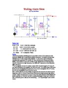
Below is a circuit diagram using a lock and unlock relay for the opening and closing of a door.
This IC does not have a key-in echo circuit, but if one was required a multi input OR gate could be used.
To set the alarm the supply must be disconnected. To achieve this a transistor switch is used to disconnect the supply when the full or part set switch is pressed. This is achieved using a NOR gate (IC2D).
UA3730
This is a 18 pin IC which uses a matrix output type keypad. The PIN number can be separately programmed directly from the keypad. This makes programming much easier. The pin layout is shown below.
The table below describes the use of each of the pins.
Below is a table for the ICs electrical characteristics.
The IC is CMOS compatible and has a key-in echo, which bleeps every time a key is pressed. The following circuit would have to be fairly complex to use this IC. Below is the circuit diagram if the IC was for use as a door opener.
Comparison of the two decoders
The choice of the decoder was based on two main factors. The first was the required complexity of the following circuit. As the RS7225 gave fixed output levels the IC could drive combination logic directly whereas the UA3730 would require special sequential logic to decode the outputs.
The second factor was cost. The cost of the two ICs is very much the same but the cost of the required keypad was much cheaper for the telephone type keypad. Also a membrane keypad was available for the telephone type which gave a level of waterproofing.
The RS7225 was therefore used.
As the RS7225 required the disconnection of the supply to reset the outputs a transistor switch has been used to disconnect the supply and reset the alarm. This is triggered by IC2D which is connected to the part set and the full set selections which switches TR1.
Alarm set indicator
The alarm set indicator is taken from pin 8 on IC1. As a warning to potential thiefs the LED was to flash on and off at a constant speed. This alerts the thief better than a constant light as a flashing light is much more obvious and more noticeable. This could be achieved by using 2 methods, a 555 counter or a different astable firing a transistor hence switching the LED on and off.
555 astable
The 555 astable is shown below.
The 555 requires an IC, 3 resistors and 2 capacitors. This method is expensive and bulky and the 555 is not very economical on the battery's charge.
The frequency of flashes can be calculated using the following equations.
f = 1.44 .
C (RA + 2 RB)
Astable using NOR buffers
By using NOR gates with buffered outputs and a RC network a square wave oscillator can be set up. This is shown in the drawing below.
The enable input would come from pin 8 on IC1 which would switch the astable on and off. When in the off state then the current consumed would be very low. When in the flashing state the current consumption would still be lower than the 555s. The frequency is equal to the multiple of the capacitance and the resistance.
This circuit only requires ½ a (Quad 2 input) NOR IC, 1 resistor, 1 capacitor, and 1 transistor (the other resistor is for current limiting the LED and would be required anyway. It is very important that the NOR gates have buffered outputs, but most CMOS ICs are buffered anyway and so this is not a deciding factor.
Comparison of LED DRIVERS
The NOR solution is the simplest and cheapest. It also has a lower current consumption and so is used. This forms IC5B and IC5A and drives LED1.
The time constant used is a 0.3 seconds giving a frequency of about 3 Hz. This is slow enough to be seen but fast enough so as it can be seen within a short time period.
This time constant was given by using a 100nF capacitor and a 3.3M resistor. These were the nearest standard values. This gave a reasonable flashing rate when tested on breadboard.
Set and Part set selection
This is the method in which part or full set mode is selected. As mentioned earlier this is to allow protection of the night lights when they are fitted and to prevent incorrect triggering if they are not fitted.
To set the alarm (regardless of part or full) IC2D was used to trigger TR1 and disconnect power from the IC. This is mentioned earlier under the PIN decoder section.
The decision for set or part set is selected by means of an RS flip-flop. The flip-flop could have been obtained by two methods. One method is to use a RS flip-flop IC this method is expensive and bulky as the IC packages contain 4 flip-flops.
The other alternatives is to create the flip-flop using NAND or NOR gates. The method that has been used in this case is to use NOR gates. This is as NOR gates were been used for the rest of the alarm system (see the section on the alarm status decoding circuit page 13).
A simple flip-flop has been used as only the Q output is required and the disallowed state will not effect the operation of the circuit. The flip-flop circuit can be seen below.
The R is the set input and the S the reset output. The Q is the output. The truth table for this flip-flop is shown below.
As can be seen from the truth table S and R both high is the state for which is not normally allowed. This is not important in my case as is not used and as Q indicates full set the alarm would be full set anyway.
Alarm status decoding circuit
The alarm status decoding circuit is the circuit which monitors the logic inputs and gives an output as to whether the alarm is to sound. This is a complex circuit and a truth table and Karnaugh map have been made up to simplify the circuit as much as possible. These are shown below.
Explanation
A = Full set state - when A=1 system in full set.
B = Part set - when C=1 part set on.
C = Lights sensors - when C=0 then lights not present.
D = Vibration sensor - when D=1 alarm should sound.
E = False combination/anti tamper - when E= 1 somebody tampering with circuit.
To simplify truth table and Karnaugh map D and E are ORed together and is therefore referred to only as D in the karnaugh map.
Truth table
Karnaugh map
The "0"s have been circled with dotted lines and the "1"s with solid lines. This gives the Boolean expression below.
Linking the "0"s Linking the "1"s
f = 1 = A.D + A.C + D.B f = 0 = A.B + A.D + C.D
In NAND only In NOR only
f = 0 = (A.D) . (A.C) . (D.B) f = 0 = A+D + A+B + C+D
f = 1 = A.D . A.C . D.B f = 1 =A+D + A+B + C+D
The above NOR only and NAND only circuits have been drawn in circuit diagram form on the following page.
NAND only circuit
The above circuit uses 4 two input NAND gates and 1 three input NAND gate. Two ICs would therefore be required for this circuit.
For the addition of the D and E the below addition would be required to replace the "D" input.
By the addition of the above circuit this would add a further 3 two input NAND gates and the circuit would then require a total of 7 two input NAND gates and 1 three input NAND gate requiring 3 ICs.
NOR only circuit
The above circuit uses 4 two input NOR gates and 1 three input NOR gate. Two ICs would therefore be required for this circuit.
For the addition of the D and E the below addition would be required to replace the "D" input.
By the addition of the above circuit this would add a further 2 two input NOR gates and the circuit would require a total of 6 two input OR gates and 1 three input OR gate which could be contained in 2 ICs.
The NOR only solution is therefore the simplest at this stage.
SR flip-flop
Some kind of latch was required for the full/part set selection. The simplest way of achieving this is to use a SR flip-flop. In a IC there is normally 4 flip-flops and to use this for only one would be a waste of PCB space as well as expensive. It was therefore required to make one using logic gates. As the S and R inputs will not be selected together (this would give both Q and Q high on a simple flip-flop which is an invalid state) a simple SR flip-flop can be used. The NAND only and NOR only flip-flops are shown below.
NAND only solution
The above flip-flop requires an additional 4 two input NAND gates and would therefore use another IC.
NOR only solution
This solution only requires 2 two input NOR gates which is ½ a 4 gate IC.
NOR only logic is used as the number of gates used is much less and less ICs are used.
Monostable hold
To give a automatic reset in the event of false triggering a circuit is to be incorporated. There are several ways in which this could be achieved but the easiest is by the use of a monostable. The monostable would be triggered by the decoding circuit and the monostable would trigger the alarm for a set length of time. This would act like a latch but would reset itself after the set length of time has passed.
One method in which a monostable can be made is by the use of a 555 timer IC. This IC allows the time to be varied easily (by changing a resistor or capacitor) and consumes very little current in the standby mode.
The circuit diagram is shown below.
For the monostable to work the resistors and capacitors have to be calculated. This is achieved by using the equations from the data sheets. The time constant to be used is 10 seconds this allows a quick reset in the event of false triggering but prevents the alarm being reset in the event of a theft.
T = 1.1 RA . C
Using a 1µF capacitor
RA = 10s
1.1 x 1µF
RA = 9090909
RA = 10M
The 555 gave an on time of approximately 10 seconds. A 10nF capacitor is used on the control pin to the zero volts rail and the reset is held high via a 330 resistor.
Sounder
The sounder could have been made in two ways. The first is to use an astable multivibrator to drive a transistor and a loudspeaker. The problem with this is that to produce a loud enough noise a very large, heavy loudspeaker is required. This also has a very high current consumption.
Instead a piezo siren was used. These have the advantage of being loud, whilst also being small and not drawing excessive currents. The one used is a miniature siren from Maplin and proved to be effectively loud.
Below is a table of the sirens current consumption at different voltages.
The siren doesn't require complex circuitry to drive it (eg an astable multivibrator) although the 555 is not capable of driving it correctly therefore a transistor switch is used. This configuration is shown below.
The BC108 was used as it is capable of driving the siren (allowing for a safety factor of 1.5) and is readily available. It has also been used previously in the circuit and so it was ordered together.
Low battery indicator
As the alarm is to be battery operated some form of indicator must be used to allow the operator to check that the batteries are not flat. The indicator should be selectable so as not to inform any potential thiefs when the battery is flattening. This is achieved by integrating the switch on the keypad. This is achieved using a transistor switch being fired by an astable multivibrator (so as to reduce current consumption by approximately half). The multivibrator uses NOR gates as the one on page 10. This transistor then switches the supply to the voltage level indicator.
There a several indicators that can be used including bargraph displays and single LED indicators that show a flat battery. To be easy to see and to make the indicator as easy to read as possible I have decided to use a tri-colour LED which can have all number of colours from green for a good battery, yellow for a suspect battery and red for a flat battery that needs replacing.
The circuit works by having zener diodes biasing transistors to come on changing the strength of the red and green elements within the LED. The circuit can be seen below.
The two zener diodes are used to set the voltage at which the battery is treated as flat. The zener diode on the left should be around 9V where as the one on the right should be around 7.5V for use on a 9V battery.
Printed Circuit Board
A printed circuit board was made for the circuit. The original intention was to make a single sided PCB but later on this proved to be impossible so a double sided PCB was made. The templates were drawn on the computer and a laser print out made. the print out was photocopied onto acetate to make a mask for photoetching the PCB. The templates used are shown below (50% actual size).
Track side
Component side
The pictures of bicycles line up on the component and track side and was used to ensure that the two sides line up.
Circuit additions
As a later thought I felt it necessary to add a further circuit to prevent the alarm from being accidently triggered when the alarm is being set or if another bike is lent against it. The circuit diagram is shown below.
The circuit will only trigger the alarm if 10 pulses pass through in the time taken for the shift register to count through which is determined by the resistor and capacitor and the astable circuit.
The circuit was built on stripboard but due to lack of time a PCB was not made.
Price list
The price list is shown below:
Problems encountered
A few problems were encountered during the construction of the circuit. These are listed below:
1\ Problems lining up the track and component side of the PCB. This was solved at the second attempt by Sellotaping the PCB to the acetate sheets.
4\ A few of the tracks on the acetate were very thin or had holes in. To overcome this the PCB had to be touched up with etch resist pen prior to etching the PCB.
3\ A connection was missing on the PCB. As there was not enough time to build the PCB again a wire link had to be connected on the underside.
4\ Two inputs to the SR flip-flop had not been tied to ground using a resistor. As there wasn't enough time to make another PCB these have been soldered onto the back of the PCB.
5\ The connectors used to change the PIN are very difficult to use and change. The connecters were chosen as they were cheap and readily available. A better connecter should have been used.