Plan:
The circuit will be supplied with 12volts. I will be using a board were you have to push the components into the holes, this will allow me to manipulate the circuit incase I have to change anything.
To test the sensor and take down recoringsI will have to use a vacuum which blows out air. I will test it from different lengths and after doing some preliminary tests I shall decide on the different lengths for my final results.
Overall I expect the circuit to work well, as the sir flow increases the voltage across the LED will also increase, thus getting a straight graph in the analysis.
Safety:
There is nothing too dangerous as I am not planning to use the soldering ion apart from the 12v voltage which should not be in contact with the mouth, it could cause an electrical shock.
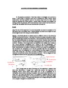
Circuit:
Below is the circuit Diagram:
The components:
The components which I used to build he circuit are shown in the table below:
Most of the components which are shown in the table were order. Not shown in the circuit diagram is the voltmeter that will be connected in parallel with the LED.
- The resistors and capacitor:
There are four resistors which I will be using, shown in the table above. The resistors are used to direct current flow to particular parts of the circuit, and used to determine the voltage gain of the amplifier. Resistors are used with the capacitor (t introduce time delays)
- The potentiometer:
The potentiometer is used to control the current in the circuit, i.e. in this case it controls the strength of the sensor.
- The Voltage Regulator:
The voltage regulator's job is to reduce the 12 volt signal to the lower voltage required by the bulb.
- The Op Amp:
The Op amp is very important component in the circuit. This is because it has seven other components connected it.
- The Incandescent lamp:
The bulb (filament) in this circuit is also very important. This is because it acts as the actual sensor of the circuit.
- The LED:
The LED will be the component which indicates the airflow. Do get a numerical reading as stated above, a voltmeter will be connected across it to measure the difference.
I will not be using the soldering ion, instead I will use a ‘push board’ were I just have to insert the components into the holes. This will allow me to replace any components that fail or even manipulate the circuit.
Results:
Preliminary tests:
After my preliminary tests I determined I would move from a distance of 2 cm until a distance of 20 cm away from the sensor, in intervals of 2 cm.
Analysis:
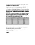
Below is a graph of the mean results I achieved from repeating the test.
The graph has a strong correlation and therefore agreeing with the predictions I had made earlier. As the Airflow gets stronger, the LED gets brighter and thus the voltage increases across the LED. The sensor worked well as demonstrated in the graph and the results.
With the line of best fit we can estimate the air flow of the vacuum at any distance. The equation of the line, worked out is y = -0.0623x + 5.7487. With this equation we can also estimate the other value when given one value, for example we can estimate the air flow of the vacuum when given the distance from the sensor. The y value would represent the voltage, and the x value would represent the distance.
Something else I noticed was t5he circuit was very sensitive to small changes in the airflow.
Evaluation:
In conclusion, the sensor worked very well, and there were not too many problems. However when I was doing my testing, rather than using a vacuum and changing the distance, a device were you can control the actual wind speed would have given more accurate results.
Over all I very happy with the way this project went. I did have to replace a few components as they got destroyed wile I doing my preliminary tests, but I had ordered spare. I got decent reading as the graph demonstrates.