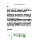
Here is a picture of my Stage 1 circuit on a bread board:
With this circuit it is possible to get up to 100,000Hz, to work out the frequency of the out put there is a simple equation that I can use it is:
Here are the values of the components I will use and the equation that I am using, here is the equation being worked out:
The output of the 555 clock circuit should be around 8.57 KHz. This graph shows the frequency of the output of the clock, but it should the frequency to be slowing that the equation says it would be this is due to the program I used.
The way that I tested the output of the 555 circuit is to use the oscilloscope to show what kind of wave is coming out of it and how fast.
This picture shows the square wave that is coming out of the 555 circuit I worked the frequency out to be around 16 KHz this is different than the
8.57 KHz that the equation worked out the frequency to be
Switch
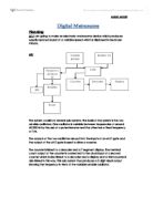
The NAND gate has an output of high for all states except for when the two inputs are high. When the switch is turned off the gate is permanently high and the counter is effectively paused, as the counter only changes state on the falling edge of a clock pulse. The output of the NAND Gate goes to the counter stage of my circuit.
Stage 2 : Counter
The counter that I have chosen to use is a 3-Bit Binary counter that is made up of 3 D-Type Flip-Flops. This diagram shows how a 1-Bit Binary counter can be made up of logic gates.
It is easily possible to make this in to a 3-Bit counter by connecting the Q’ to the clock of the next set of logic gates. This diagram shows the 3-Bit Binary Counter it can be easily be changed in to a 4-Bit Binary Counter by adding another D-type Flip-Flop in the same arrangement as the others.
This picture shows my stage 2 circuit on a bread board:
The next two tables show what the number will be with each possible combination from the three outputs of the 3-Bit Binary Counter.
There are two states that are not needed but it is possible for them to appear as the output these are:
By using logic gates it is possible to make the flip-flops reset when these states appear so that it is not possible for the dice to land on them.
To test the second stage of my circuit which is the 3-bit binary counter that I have made out of flip-flops I will test each of the outputs of it (A, B, C)
Output of A
This picture shows the output of A it is half the frequency of the clock
Output of B
This picture shows the output of B it shows that the chip has not got enough time in-between each clock pulse to change from high to low or low to high so the output if B is always towards the
Output of C
This picture shows the output of C. Due to the output of B, C has the same kind of problem.
Stage 3 : Logic Gates
The three outputs from the 3-Bit Binary Counter go to the logic gates and seven segment display, the logic gate control the rest for the 3-bit Binary counter and they also make sure that the seven segment display only displays numbers from 1 to 6. if all of the outputs from the 3-Bit Binary counter are high then the counter is reset. Once all the outputs are low the next set of logic gates force output A to be high and with B and C still being low the seven segment display would display one.
This arrangement of logic gate prevents the illegal states that are 0, 7. When B, C and D are all high or all low then the Flip-Flops are reset.
Time graph
This time graph shows the outputs of the 3 D-Type Flip-Flops in the Circuit. It shows that the output of the first flip-flop is half the speed of the clock. And the second flip-flop is half of the output of the first flip-flop, and the output of the third flip-flop is half the output of the second flip-flop.
WONT WORK (need to change the logic gate network)
I am going to have to change the logic gate network for my 1-6 dice because it will always be zero due to the logic gate network resetting the flip-flops every time it is zero or seven and once it is reset it will keep getting reset so there for will always be on zero.
This diagram below shows how a simple change can make my circuit work like it should do.
to cut down on the amount or IC’s I was going to use I have change the way that I make my logic network instead if using A 3 INOUT and gate I will use this combination that will do the same thing:
This will cut down the IC’s that I have to use from 7 to 6.
Stage 4 : LED Layout
I have design an arrangement of LED that will give the look of a real dice I will use this instead of the 7 segment display, this diagram sows how the LED’s should be set up:
Here is how the light will show up the different numbers:
Final Testing
When all put together my circuit and tested it to see if I could get a number out of it I notice that the LED’s did not light up very well, I kept testing my dice to make sure it was that it was not staying on one number all the time
When I did this I notice that the only numbers that come up were 2, 3 and 6.
7 never come up so I can say that my logic gate system works.
Extra-lights
It would be possible to have a light display on the dice so when the user gets a 6 a light sequence would trigger, 6 is would be the number to trigger it because in most board games getting a 6 would mean getting another go or some thing special happening. A light display could show you when you got a 6
The LED arrangement will look like this:
The LED’s will light up when a 6 is displayed they should also flash very fast while the numbers are being cycled.
Here is the full circuit diagram for my electronic dice:
Here is a picture of the full circuit on a bread board:
Evaluation
I think that the reason that I am only getting 2, 3 and 6 is because that output B is always high, if I were to slow the clock down to about 5KHz that the 3-bit binary counter would work like it should do and output B would go from high to low like it should that way it will cycle through the number like it should.
I have an idea that may make the LED’s light brighter this is to make a transistor switch before each LED. It would like this for each LED:
I put in one LED for system to recognize when a 6 was rolled but I was very dimly lit, it would be possible to put a transistor in front of this LED as well to sort this problem out.
Here is the full circuit diagram for my electronic dice:
Specifications
- For all of the LED’s I am using the voltage that needed to light was 2 volts
- All IC’s (integrated Circuits) I am using should be powered by at least 5 Volts
PIN Layout
Here are the pin layouts for all the IC’s that I used.