I predict that with this principle, the mass acting upon the sensor will move the moving contact therefore changing the output voltage, which then will be measured in relation to the mass.
Equipment
- Linear position sensor (linear potentiometer)
- Leads/wires
- Protective Perspex cylinder
- Weights (masses)
- Plastic box (base)
- Digital MultiMate
- Small circular plate
- String
- Power supply
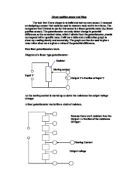
Diagram of design and construction of my sensor
String Perspex Cylinder
Mass
Moving contact
Digital
Multimeter
Plastic box
Circuit
Resistor
Moving contact
Input V
V Output V a fraction of input V
I already know that as the mass increases the output voltage will become higher
Factors about the sensor:
Resistance 5KΩ linear
Linearity 2%
Temp. Coefficient 0 to 200ppm/◦C
Output smoothness 0.5% max
Operating Temp. –40 to 130 C
Mechanical travel 12.5mm
Operating force 2 to 7N
Mechanical life 5 x 10 full cycles
From this information I have decided the following
- I should carry out the testing at room temperature. (20-27 C) because it is well within the boundaries of the coefficient temperature of the sensor.
- The sensor has an operating force of 2 to7N therefore I should start with 2N or 200g and increase in 0.1N or 10g each time.
- The sensor has a mechanical travel of 12.5mm so there will be a maximum weight restriction; this means that I can only take a limited amount of readings.
- I will take two sets of readings, one for the mass and one for the voltage.
METHOD
- The sensors operating force ranges from 200g to 700g, therefore I will start by using 200g and take a reading, and then gradually I will increase in masses of 10g to 700g.
- Using string I will lower the weights down onto the centre of the plate. This should ensure that all the mass’s weight is acting on the moving contact and not on the protective Perspex cylinder.
- The digital multimeter may fluctuate so I will allow a period of 15 seconds after placing the weights before taking a reading.
- I will take all readings to four significant figures. This should give me more reliable results
- I will repeat the process three times so that I can obtain an average so that the results obtained are more accurate.
ANALYSIS
From the table and the graph, it is clear to see that there is a relationship between the output voltage and the mass acting upon the moving contact. The straight line on the graph shows this relationship. Therefore I can definitely say that the output voltage increases proportionally as the mass is increased.
The straight line can be explained using the physics involved in a linear resistor and potentiometer. A mass potentiometer consists of a linear resistor, on which a moving contact is put on. The resistor and the contact are placed in two circuits so that a value for the output voltage is gained via the position of the moving contact, on the linear resistor. I was given the straight line due to my choosing of the steadily increasing mass. (I.e. each 10g that added the value of the output voltage increased steadily)
Therefore I can say that the resistance increases steadily in proportion to the mass acting on the moving contact. This is supported by the graph.
The output voltage values starts to level out towards 700g. This can be explained by knowing the factors of the sensor. The potentiometer that I used has an operating force of 2N to 7N (200g –700g) and a mechanical travel of 12.5mm. This means that the moving contact has reached the maximum travel, at this point maximum resistance is being encountered and the output voltage stays the same.
EVALUATION:
I feel that the experiment was successful in that I obtained fairly reliable results that gave me a clear outcome. The results gained fit the line but there were some minor anomalies in the results.
Taking three sets of results and finding an average avoided inaccuracy.
I used masses less than 10N for safety reasons. The fact that the sensor had a Perspex cylinder to prevent the masses from falling off the moving contact heavier masses could cause the sensor to topple, causing a safety hazard. I also had to take into consideration the fact that the sensitivity of the mass potentiometer had a maximum of 700g where the maximum output voltage was reached. Therefore 10g mass divisions were used to provide a sufficient spread of results.
Some of the anomalies may have occurred when reading the output voltage.
The voltmeter only read to 3 decimal places plus it fluctuated constantly between close readings i.e. 130v to 140v. The reading ceased to stop fluctuating so a reading was taken after 15 seconds after the weights had been placed on the sensor.
One problem that occurred was trying to rest or balance the weights on the small surface area of the moving contact. This was overcome by placing a Perspex cylinder over the sensor so that the weights would not topple off the moving contact as shown on diagram.
Unstable Stable
Although the weights rested on the cylinder and a minor portion of the weight transference occurred with the cylinder I feel that this had minimal effect to the outcome.
USES OF MY SENSOR
There are many uses for my sensor, two of which I feel would benefit the most would have to be
1: A burglar alarm
2: Weighing scales
These two pieces of equipment would make use of the relationship between mass and voltage, i.e. giving a voltage reading in relation to the mass of an object.
Scales:
My sensor would not be able to cope with ordinary household bathroom scales because it has a maximum force of 7.5N, which is about the same weight as a newborn baby. So by making a larger model with a higher working force would ensure it was suitable for bathroom scales.
The system would work exactly like the experiment except there would be a person instead of the weights. The person would stand two footed on the sensor and the moving contact would move down. Depending on the weight (mass) of the person a voltage reading would then register in the programme chip. This definite value of the voltage is then converted into a mass and displayed on the digital unit. The resolution of the sensor would make it sensitive enough but the fluctuations would make it impossible to get an exact reading so the scales should be programmed to deal with the fluctuations and take an average of 6 readings.
Burglar Alarm
My sensor is suitable to be used for a burglar alarm pad because once an intruder exerts a force on the pad sensor it moves the moving contact and there is a voltage output. This voltage reading then triggers off the sound system.
The moving contact is small on my sensor so it would not be suitable for a burglar alarm because there is less chance that an intruder would manage to make contact with it. Therefore the pad / moving contact must have a large surface area increasing the chance of an intruder stepping on it.
The sensor has a virtually instantaneous response time. This aspect is crucial for a burglar alarm pressure pad because the intruder could tip toe across the sensor quickly and the sensor has to be able to be rapid enough to be effective.
Problems may occur if the sensor was programmed to respond to any mass. If the sensor was placed in the house a household pet such as a cat or dog easily triggers it. Therefore the sensor system must be modified to take into account the mass of household pets. Setting the alarm to respond to a certain optimum voltage could do this. E.g. anything less than 60Kg could walk on the pad without setting the alarm off. This system has an advantage over infrared-based alarms because it could be activated or turned on with the pets in the house/room.