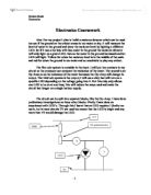
The circuit can be split into separate blocks, like the Op-Amp. I have done preliminary investigations on these other blocks. Firstly I have done an experiment with LED’s. Through this I learnt that an LED requires 1.8volts too work, but in most circuits 2V are used too ensure that the LED is bright and any more than 5V would damage the LED.
The diagram above is my preliminary investigation using LED’s, by changing the 5K potentiometer the light will have more voltage or less voltage. The 100 Ω resistor protects the LED, so not too much current is allowed through. By doing this preliminary investigation I knew that I could use LED’s in my circuit, as I would have between 1.8V and 5V for them to run off.
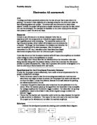
Secondly, I have also investigated the Op-Amp before. In a circuit with an Op-Amp (see diagram below) there are two resistors which hold the voltage for the non-inverting input (pin 3), these two stay the same. Then for the inverting input (pin 2) there is one resistor and a variable resistor, which can change the voltage allowed through it. As the voltage between the two resistors for the inverting input changes, from high to low then the output will change. If the input is high then the Op-Amp will invert the output signal (pin 6) so the output will be –5V. If the input is low then the Op-Amp will non-invert the output, so the output will be +5V. This could then be used as a switch in my final circuit by connecting it to two contacts which will change there resistance depending if there is any water present and the Op-Amp can connect to LED’s which will light. I also used ‘Introducing Electronic Systems’ by M.W. Brimicombe. This reference book contains all the systems and circuits that I will need.
Specification: my circuit must
- Detect the moisture in the ground, between dry and very wet. This will give the user of my circuit an accurate reading of the moisture level.
- Make LED’s light when moisture increases. A simple and effective display, at low moisture levels only one green LED will light. Then at wetter levels more LED’s will light, then when it is too wet the circuit will turn on three red LED’s, warning the user.
- Draw as little current as possible, less than 50mA. This will increase the amount of time the circuit can be run off a single battery.
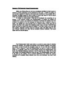
Block diagram of proposed system:
The input will just be the two contacts that are put in the ground. Depending on the resistance of the water a signal is feed into the Op-Amp. Then the Op-Amp will send a high or low signal into an IC chip that will display the relevantly coloured LED.
My circuit is restricted, as I could build a circuit that has an Op-Amp for each LED. But this would take too long and make fault finding extremely difficult. Only the cost is not restricting, as even if I built an Op-Amp for each it would still be very cheap to do so.