Using a Rotary Potentiometer to Detect the Position of a Robotic Arm
Plan:
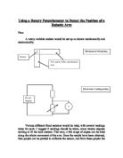
A rotary variable resistor would be set up as shown mechanically and electronically:
Various different fixed resistors would be tried, with several readings taken for each. I suggest 9 readings should be taken, every twenty degrees starting at 20 for each resistor. That way, a full range of angles can be tried along the whole movement of the arm. Once the results have been obtained, then graphs can be plotted to calibrate the sensor, and from these graphs the most suitable resistor can be chosen for the sensor involved. Initial experiments show that all readings will be in the range of 0 to 5 volts.
Results:

I took three sets of results. They were all exceptionally similar. As such, they have been compiled into one single table, which is the average of the three results for each resistor at each value. As the results were so similar, I did not deem it necessary to display each and every reading in this report. Please note that more than 9 readings were taken. This is because it did not seem that a full set was taken after 180 degrees, so I changed my plan accordingly, to allow readings over the entire range of the sensor (300 degrees).
...This is a preview of the whole essay
I took three sets of results. They were all exceptionally similar. As such, they have been compiled into one single table, which is the average of the three results for each resistor at each value. As the results were so similar, I did not deem it necessary to display each and every reading in this report. Please note that more than 9 readings were taken. This is because it did not seem that a full set was taken after 180 degrees, so I changed my plan accordingly, to allow readings over the entire range of the sensor (300 degrees).
Analysis:
The range is simply the range for each resistor’s values. The larger this value is, the better, as it means a greater resolution and larger difference of voltage between two different angles of the arm. As such it would make it easier to measure and result in more accurate movement.
SD stands for standard deviation, and is the measure of the average spread of the data. A larger standard deviation is most desirable, as this means that the data is spread more evenly, and most linearly (results were taken very frequently, and a significant amount of ‘plateau’ can be seen, lowering the SD of the resistors which yielded the least even spread. For example, the 100-ohm resistor has 12 readings less than 0.5 volts apart. This results in a low SD, even though the spread is less even). I have also divided the standard deviation by the range to allow for comparison between resistors of different ranges, and quantitative comparison. A larger graph that better depicts these readings is in the appendix. Again, the higher the SD/Range ratio the better for a generalist arm. However, I believe that range should also be maximized, and as such I believe the 2.2kΩ is the most effective in this role (see below). Linear variation is most desirable for this use in a non-specialist arm.
This is beneficial, in a typical arm, because a large and even difference in voltage is present wherever the arm in its arc. A more specialized arm, for example in a car factory, might need great accuracy in a certain position, such as near the car, and less accuracy in others, like storage position, and well above the car. This arm would require a large spread of potential difference over certain angles, and smaller spread of potential difference over others. Just looking at the results shows that such performance is demonstrated in resistors of lower resistance. For example, in the extreme case, the 100-ohm resistor has a change of almost three volts between 20 and 40 degrees. This results in a resolution of a fourteenth of a degree (1), or just over a millimetre up or down at 1 metre (2), an almost imperceptible change of angle. Considering the equipment used is only standard and simple, I find this quite impressive. It is certainly more than is needed for a typical robotic arm.
Note, to see the mathematics involved in any of the figures I give, see the appendix at the end of this paper. The figures in brackets relates to the subsection in the appendix.
In general, I have learnt that a normal rotary resistor is more than adequate for use in most robotic arms. In order to get generalized and high accuracy results, choose a resistor that has a value similar to that of the rotary resistor itself (in this case, the 2.2kΩ resistor yielded the best general results), or if extreme accuracy is needed over a smaller range, a lower value resistor can give phenomenal accuracy over a range from a few degrees to about 20 or 30. The resistor would have to be installed at the correct orientation and amount of turn beforehand to ensure that the sensitive region is correctly aligned with the needs of its use.
If money and simplicity is less important, and extreme accuracy is needed over a larger range, two or more resistors of relatively low resistance could be installed on the same axle, so that the regions of highly rapid change overlap over a wider angle, and a computer system arranged so that the right resistor is used at the appropriate time. Such a system would need to be calibrated exceptionally well, and I believe it would not respond well to shock and vibration. Its accuracy and range would be extremely good, however.
Response time of the system was around 1 second. It was this poor due to the voltmeter used. The sensor itself had a very low response time. If linked into a different voltmeter, or logic circuitry, the response time would no longer be a problem, as the voltmeter that causes the delay has been removed entirely. In addition, there was no drift of the readings, as long as the arm was bound well enough to the sensor, and the extreme repeatability (near zero random variation) of the sensor means it would be very reliable as the position indicator for a robotic arm.
I will end on the limitations to this project. It cannot consider the effects of time and age on the sensor, its reliability under adverse conditions such as varying temperature, vibration, shock, and water resistance. It did not compare the advantages of other rotary potentiometers over this one, either.
Appendix:
- 3.14-0.35 = 2.79
2.79*100 = 279 (as the voltmeter used was accurate to 0.01 volts)
279/20 = 13.95
1/13.95 ≈ one fourteenth
- 180*13.95 = 2511
∏/2511 = 0.001251132
0.001251132 * 1000 * 1 ≈ one millimetre at 1 metre