The 'fragment offset' is also used for reassembly of the packets, and indicates where the data within a small packet belongs in relation to the original packet payload.
The 'time-to-live' field defines the maximum amount of time in seconds that a packet can be in motion on the Internet.
The 'protocol' field defines the protocol being used, e.g. TCP, UDP.
The 'header checksum' field is used for error detection, and ensures that packets that have become corrupted, do not get sent to the wrong destination.
The 'source address' and 'destination address' fields contain the IP addresses of the source and destination hosts.
The 'options' field is used optionally by a datagram to carry information regarding encryption security, specific routing details, etc.
The standard protocol for Internet communication is known as TCP/IP.
TCP (Transmission Control Protocol) / IP (Internetworking Protocol). The TCP protocol is responsible for breaking the data up into the packets, reassembling them in the right order at the recipient end, and re-sending anything that doesn't arrive. The IP protocol is responsible for routing the packets to the recipient, it isn't concerned with what the packet contains, its sole responsibility is to find a route for the packet and to get it to the other end.
In order for a computer to send a packet to a remote recipient, it first ensures that the recipient is not on its own local network, and if so forwards it to a router. Every computer that has access to the Internet has access to a router (gateway). A gateway is a system that connects a network with one or more other networks, and is normally just a computer with more than one network interface. The router or gateway, contains a list or table of all other routers that are visible on the Internet, the information contained in this routing table is used to find the best available route to forward the packet to the destination via the appropriate intermediate routers.
These routing and forwarding operations used by the gateways are performed at the 'network layer', or IP, in the TCP/IP protocol stack. For information to be passed from one host to another, the IP has to be known to both the source and the destination hosts, and to any intermediate gateways involved. The diagram overleaf illustrates the network layer protocol.
Network Components and Protocols of the Internet
Source Destination
= logical communication path of PDUs.
= actual path of PDUs.
TCP/UDP = transmission control protocol/user datagram protocol.
PDU = protocol data unit.
IP = internet protocol.
LP = link protocol.
PL = physical layer.
Ipv4 Addressing and its Limitations
As mentioned earlier, each host that communicates over the Internet has a unique Internet wide address assigned to it. This is known as the host's IP address. Each IP address consists of two parts; a 'network identifier (netid)', and a 'host identifier (hostid)'. Netids' are managed and allocated by the Internet Network Information Centre (InterNIC), and each access network, e.g. ISP, campus, has a unique netid assigned to it. Hostids' are then assigned to each of the hosts on a network, by the network administrator of the access network.
Ipv4 encompasses three main different address formats, known as address classes (A, B, and C). Each class is used for a different size of network.
Class A addresses are intended for use with large networks of up to 224 (16 777 214) hosts attached, class B addresses are for use with networks of up to 65 534 hosts attached, and class C addresses allow up to 254 hosts attached to a network. Classes A, B, and C are known as unicast addresses, which means that the datagram (packet) will be passed through the network and delivered to one address.
As well as the A, B, and C classes, there are also two other classes, D, and E. These are used for group/broadcast addressing, class D's being assigned dynamically as and when required, and class E's being reserved for experimental use.
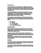
The diagram below illustrates these address classes.
IP address formats
Class A
As shown in the diagram above, Class A network addresses use an 8-bit network-prefix, with the highest order bit set to 0 and a 7-bit netid. As it has an 8-bit network-prefix, class A can define a maximum of 126 networks (27 - 2, the minus 2 is needed because networks 0.0.0.0 and 127.0.0.0 are reserved for other functions). The network-prefix is followed by a 24-bit hostid, which means that each of the class A networks can have up to 16 777 214 hosts (224) attached. The 126 Class A networks are used by very large commercial companies, the ARPAnet being one, and use 50% of the total IPv4 unicast address space.
Class B network addresses have a 16-bit network-prefix, with the two highest order bits being set to 1-0 and a 14-bit netid. As it has a 16-bit network-prefix, class B can define 16 384 networks (214). This is followed by a 16-bit hostid, meaning that each of the
16 384 networks can have up to 65 534 hosts(216 - 2) attached. Normal large organisations use class B network addressing, and it represents 25% of the total IPv4 unicast address space.
Class C network addresses have a 24-bit network prefix, the three highest order bits being set to 1-1-0 and a 21-bit netid. Having a 24-bit network-prefix, class C can define 2097 152 networks (221). This is followed by an 8-bit hostid, meaning that each network can have up to 254 hosts (28 - 2) attached. Class C network addressing represents 12.5% of the total IPv4 unicast address space.
As already mentioned, Internet addresses (IP addresses) are 32-bit numbers. To make these numbers easier for humans' to understand they are often broken down into four bytes, which are then converted into four decimal numbers, each separated by a dot. This is known as 'Dotted-Decimal notation. For example:
1) 00000110 00000000 00000010 00000101 = 6.0.2.5
The highest order bit is set to 0, therefore it is a class A address.
Netid = 6
Hostid = 0.2.5
- 10000000 00001100 00000011 00001011 = 128.12.3.11
The two highest order bits are set to 1-0, therefore it is a class B address.
Netid = 128.12
Hostid = 3.11
In the Internets' early days, this class address format seemed ideal, the address format was easy to understand and implement, and at the time it seemed to allow unlimited address space. But the past few years have seen an ever-increasing growth of the Internet, and two major problems have arisen regarding this growth.
The first of these scalability problems is the pending exhaustion of the Ipv4 address space. A few years ago IP addresses were being freely handed out to anybody who asked for them, with no regard to the idea that they would eventually run out.
The depletion of the Ipv4 address space has also been hugely aggravated due to the un-flexibility of the class address format boundaries. Many network sites found that class C, which provides for 254 hosts, was too small, while a class B, which provides for 65 534 hosts, was far too large. This meant that networks containing just a few hundred hosts, that were too large for a class C addressing structure, were being allocated a class B addressing structure. This has resulted in thousands of wasted addresses, and has brought about a second major scalability problem - the premature depletion of class B address formats.
The depletion of class B address formats means that medium sized organisations can now only be offered class C addresses, meaning that one organisation may need more than one netid.
This has the effect of hugely increasing the Internet's routing tables, which brings with it an ever-increasing maintenance overhead in the constant reconfiguration of these routing tables. It has also had an effect on the routers themselves, in that they have had to become more powerful, in terms of processing power, memory, and speed, in order to maintain performance. However, they are currently fighting a losing battle as routing tables are increasing in size faster than the routers can map, and if the growth of these routing tables is allowed to continue it could result in parts of the Internet becoming unreachable.
As these problems started to become critical, an attempt to alleviate them came in the form of an alternative type of routing, called Classless Inter-Domain Routing (CIDR). The main aim of CIDR was to make efficient use of the remaining network address space, and to minimise the growth of the Internets routing tables.
CIDR makes efficient use of the many remaining class C addresses, by eliminating the traditional method of the class A, B, and C address spaces. This was achieved by abandoning the fixed netid/hostid boundary, and employing a variable boundary that is dependent on the number of hosts attached to a network. Thus if a network manager requests addresses for a network that will have 1000 hosts, then a contiguous block of 1024 (210) class C addresses can be allocated.
The variable boundary is achieved by the use of an address mask. The address mask is used to identify the division between the netid and hostid part of the address.
Each gateway contains a copy of the address masks for each of the networks and uses this to route the packets to their destination, this allows for a single routing table entry to specify the routes to many individual networks.
Although CIDR has been effective in stemming the depletion of address spaces, and the growth of the Internet's routing tables, it is clear that it cannot prevent the eventual exhaustion of the 32-bit Ipv4 address space.
The solution to this problem comes in the form of a new version of the Internet; Ipv6.
Ipv6 In Detail
Ipv6 is effectively a new protocol, and although it has been designed mainly to provide a solution to the limited address space problem, it also includes many other features, which take care of other deficiencies associated with Ipv4. The following is a list of the new features of Ipv6:
- Increased address space of 128-bits.
- A hierarchical address structure to reduce the size of the Internets routing
tables.
- A simplified packet header to enable faster processing and routing of packets.
- Autoconfiguration of IP addresses.
- Improved security and data integrity facilities.
IPV6 datagram format
The format of the Ipv6 datagram/packet header is different to the Ipv4 datagram header in that it contains fewer fields, and has been somewhat simplified. Where Ipv4 headers were variable in length, the Ipv6 header is of a fixed length of 40 bytes. The following diagram illustrates the Ipv6 datagram format.
Ipv6 packet/datagram format
1 2 3 4 5 6 7 8 9 10 11 12 13 14 15 16 17 18 19 20 21 22 23 24 25 26 27 28 29 30 31 32
The only similarities between the Ipv4 and Ipv6 headers are the version number field, and the source/destination fields.
The 'traffic class' field is similar to the v4 TOS field in that it allows the source IP to allocate different priorities to different types of applications.
The 'flow length' field is a new field that is used in conjunction with the traffic class field to reserve paths for individual packets relating to the same session/flow.
The 'payload length' field is similar to the total length field of v4, except that the value does not need to include the header length, as this is fixed.
Ipv6 datagrams have a facility for extension headers to be inserted between the main header and the transport protocol header. Extension headers have replaced the v4 options field, and include information regarding security, routing, fragmentation, etc. The 'next header' field indicates the type of header that follows.
The 'hop limit' field is basically the same as the time to live field from Ipv4, in that it defines and decrements the time that a packet has to live.
The Ipv6 Address Structure
The design of the Ipv6 address structure is hierarchical, and as such is similar to the design of telephone networks, which have a hierarchy consisting of country, region, exchange code and a local number. This type of hierarchical routing, is known as address aggregation, and results in much smaller routing tables as all calls with the same preceding codes are routed in the same way.
However, unlike telephone networks, the Ipv6 hierarchy is not just constrained to geography. Ipv6's huge address space allows for a number of different address formats, such as unicast, multicast, etc. The format of the address is identified by the first set of bits (prefix format) in the address, the following table illustrates the different address formats and their assigned prefixes.
Prefix Formats and address use
The current structure of the Internet enforces Provider-based unicast addresses as the most widely used format.
At the very top of the hierarchical addressing structure, there are several international registries, such as the European registry and the North American registry. The registries allocate large blocks of addresses to top-level aggregators (TLAs). The Internets core backbone consists of high bandwidth lines that connect the continental backbones together, and these top-level aggregators are companies who own the routers that perform this major function.
The TLAs then allocate blocks of addresses to next-level aggregators (NLAs). NLAs are large Internet service providers and global enterprises, who operate at a continental, national and regional level. The NLAs then allocate addresses to large businesses, single individual subscribers, and smaller regional or national ISPs. These are called the site-level aggregators (SLAs). The following diagram illustrates the provider-based unicast address format.
Provider-based unicast address format
TLA = top-level aggregator.
NLA = next-level aggregator.
SLA = site-level aggregator.
As we can see from the above diagram, the first 3 bits of the address indicate that the address is a provider-based unicast address.
The next 5 bits indicate which registry supplied the address.
Then the next 8 bits are allocated for the TLAs.
The 8 bits following the TLA block are reserved for future use.
The various worldwide NLAs have been allocated the next 24 bits. This provides the facility for the field to be further divided, allowing the NLAs to create their own hierarchy, of smaller and larger NLAs.
The remaining 2 fields, the SLA and Interface ID fields, are used for subscriber site networking information, and can be used by organisations to create their own hierarchy comprising subnets and hosts.
The provider-based unicast address format allows for very efficient routing, as NLAs that are under the same TLA have addresses with the same TLA prefix, and subscribers of one particular provider will all have addresses with the same NLA prefix.
The geographic-based unicast address format works generally in the same fashion, except that whereas Provider allocation divides the hierarchy up into large service providers independent of location, geographic allocation divides the hierarchy on the basis of the location of providers and subscribers.
The flexibility of Ipv6 means that it can also provide other address range formats (as shown in prefix-format table above) for multicasting, site-local and link-local use, and the embedding of other addresses.
The Move to Ipv6
Some suggest that Ipv6 should be adopted as soon as possible, whereas others feel that its adoption should wait until all of the Ipv4 addresses are exhausted, either way the move to Ipv6 from Ipv4 cannot happen overnight.
The equipment that makes up the Ipv4 Internet is spread worldwide. Therefore the introduction of Ipv6 has to be carried out incrementally, which means that there must be an efficient standard of interoperability between the new Ipv6 equipment and the existing Ipv4 equipment, at both the address and protocol level, for an undefined period of time.
Ipv6 designers have spent a great deal of time ensuring that upgrades to Ipv6 will be as smooth as possible, and have specified techniques which will accomplish this compatibility. These techniques include dual-stack hosts and gateways, and tunnelling Ipv6 over Ipv4.
A dual-stack host is a computer that is able to handle dissimilar protocol stacks.
I.e. In a site that contains both Ipv4 and Ipv6 hosts, the server must contain the Ipv4 and Ipv6 protocol at the network layer, to be able to handle requests from both types of hosts.
In a similar way, a gateway that connects an Ipv6 network to the Ipv4 network must have a dual stack, each of which has a corresponding v4/v6 address to allow communication between two Ipv6 networks (sometimes referred to as Ipv6 islands) over the Ipv4 network. The process of transferring the Ipv6 packets over the Ipv4 network is known as tunnelling. The diagram overleaf illustrates this approach.
Packet Transfer using dual-stacks and tunnelling
In order to achieve this type of communication, the Ipv6 packet has to be transferred between its own dual-stack gateway, and the receiving dual-stack gateway, within an Ipv4 packet.
The Ipv6 protocol in each gateway first determines from its routing table whether the v6 packet is to be transferred over a v4 network. If so, it passes the packet, with the v4 address of the receiving gateway, to the Ipv4 protocol. The Ipv4 protocol then puts the v6 packet into the payload part of a v4 packet, and embeds the remote gateway v4 address into the v6 address in the destination field of the v4 packet. The remote v4 address is then used to route the packet to its destination.
Upon receipt of the packet, the Ipv4 protocol in the remote gateway determines from its routing table that the packet has been tunnelled, strips off the Ipv4 header, and passes the payload part to the Ipv6 protocol, where it is forwarded to the destination host.
As shown earlier, in the prefix-format table, Ipv6 has an address format, which allows Ipv4 addresses to be embedded within it. The diagram below illustrates the embedded Ipv4 addressing structure, for communication using dual-stacks and tunnelling.
Another requirement of the interoperability of Ipv4 and Ipv6 is that a host attached to an Ipv6 network will be able to communicate with a host from an Ipv4 network. Both of the hosts will have different address and packet formats: the Ipv6 host has an Ipv6 address and is using the Ipv6 protocol, and the Ipv4 host has an Ipv4 address and is using the Ipv4 protocol.
This type of communication is carried out in a similar way to that described above, but because of the different address formats, a translation function is needed. This is carried out by the immediate routers/gateways, using a 'network address translator' and a 'protocol translator', which converts the packet to the required packet format for the recipient. The following diagram illustrates this procedure:
Interoperability using Translators at Network Level
Host Host
As explained earlier Ipv6 has address formats for allowing v4 addresses to be embedded within v6 addresses. For communication between a v4 host and a v6 host, the v4 address is preceded with 96 0s. The diagram below illustrates this format.
Other Advantages of Ipv6
As well as an increased address space and much improved and automated routing process, the designers of Ipv6 have also added other features that are not present in Ipv4, or have improved features that were inefficient in Ipv4.
Security Issues
Ipv6 has a variety of extension headers. Two of these are used for the security of data as it is transferred across networks. One extension header, known as the 'Authentication' header, contains authentication information, which enables the recipient of data to verify the authenticity of the source. The other header, which is called the 'Encapsulating Security Payload' header contains information which allows the encryption and decryption of a datagram, by both the source and recipient.
There are two levels of security, the first method is called transport mode encryption, where only the payload is required to be encrypted, and the second is known as tunnel mode encryption, where the whole of the data packet including headers is to be encrypted. The second method provides increased security, as the routing headers are not visible over the Internet, this method is referred to as a steel pipe connection
The security is achieved by passing an encryption algorithm between the two hosts, and the exchanging of dynamic security keys.
This improves the current situation with Ipv4, which has no major security facilities, and is open to attacks by hackers who pass themselves off as the destination IP.
Autoconfiguration
With Ipv4, the allocation, installation, and administration of IP addresses involves a considerable amount of manual effort and cost. Therefore some Ipv4 networks use the Dynamic Host Configuration protocol to assist in the configuration process.
Dynamic Host Configuration Protocol (DHCP) is known as a stateful address configuration tool, because it maintains tables that determine which addresses have been allocated to new networks.
The designers of Ipv6 have created a new version of DHCP, called DHCPv6. DHCPv6 not only eases initial address configuration, which enables a host to obtain an address via the network dynamically, but also has an address reconfiguration facility which allows migratory, simultaneous address re-numbering of whole sites.
The facility will also be able to configure temporary addresses for users of mobile computing, such as laptops.
Conclusion
Ipv6 has many features and benefits over and above those provided by IPv4. Network Administrators are looking to provide robust, scalable, secure, high performance networks. This is proving difficult to achieve due to the continual requirement to update routers performance and routing tables, most of which is manually done. The issue of gaining a suitable IP address for sufficient users is not as easy now due to the depletion of available IP addresses.
Subsequently when this is not possible the technological 'workaround' such as that provided by CIDR or NAT's means not all of your network is visible to the larger Internet and potentially bottlenecked, as all traffic has to pass through the translator before it can get onto a router.
The ability of Ipv6 to allow auto configuration of routers and host Ipv6 addresses significantly reduces maintenance times and effort.
Ipv6 is more efficient in terms of network traffic loads due to its ability to Unicast and Multicast along defined hierarchical routes.
Ipv6's bit size and format allows for future development and with almost unlimited scalability and security should serve well as a standard for the foreseeable future
The very fact that Ipv4 is insecure and open to misuse should be reasons enough to cause a conversion as soon, as is economically viable.
The only major downside is the requirement to providing Dual stack Routers to enable the migration of data between IP versions whilst the two protocols remain in operation.
Ultimately all networks will have to convert to Ipv6 because demand for IP addresses will continue to rise as more devices and technologies place demands on a finite resource.
On a final note, it was found that Network protocols and their functionality is a major issue for businesses whose primary function is data transfer. For them to remain competitive they have to have efficient, secure and reliable communication methods.
Bibliography
Books
Fred Halsall, "Multimedia Communications - Applications, Networks, Protocols and Standards", Addison Wesley, Pearson Education Limited, 2001.
Deitel, Deitel & Nieto, "e-Business & e-Commerce - How To Program", Prentice Hall, 2001.
Andrew Ford, "Spinning the Web - How to Provide Information on the Internet", International Thompson Publishing, 1995.
Currid & Currid, "Novell's Introduction to Networking", Novell Press, 1997.
Internet
Chuck Semeria, "Understanding IP Addressing - Everything you ever wanted to know", , 2000.
Bob Melford, "TCP/IP Limitations Undone", , Unix Insider, December 2000.
King et. Al., "The Case for Ipv6", ,
Internet Architecture Board, June 2000.
Charles l. Hedrick, "Introduction to the Internet Protocols", , Computer Science Facilities Group, State University of New Jersey, February 2001.