Figure 6. Figure 7
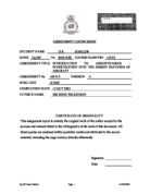
10. If a straight wing with a MCRIT number of 0.7 is studied, this is the flight Mach number at which sonic flow will appear at some point on the wing. This will cause shock waves to appear on the wing leading to rapid increases in wave drag. If the same wing has a swept leading edge to an angle of 40o and the flow vectors calculated, the component normal to the leading edge, V Cos Λ, is markedly less than the TAS, 0.7 Cos 40o = Mach 0.54. This can then be manipulated to show the Mach number at which MCRIT will appear, M = 0.7 / Cos 40o = 0.91. This shows that a wing with 40o sweep can reach speeds of up to Mach 0.91 before sonic flow appears. Any further sweep will delay the onset of sonic flow and associated drag rise to even higher Mach numbers.
Figure 8. Sweep compared to Mach number
High Angle of Attack Performance.
11. One of the essential requirements of an air superiority fighter is the ability to engage in high angle of attack manoeuvres with control. The F-15 has been designed with this in mind and has a number of features to assist high angle of attack manoeuvres.
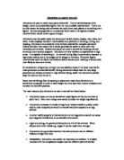
a. Strakes. Strakes are a relatively new concept in combat aircraft design and are used to great effect on aircraft such as the F-16 and F-18. A wing strake has little effect at low angles of attack but as the angle of attack increases, the wing strake causes a vortex to be generated. This vortex moves out over the wing and suppresses the stagnant zone as the angle of attack increases and ensures lift is maintained. These strakes, in conjunction with the upper surface of the engine air intakes will induce a vortex which will maintain lift to very high angles of attack.
Figure 9. Lift gained due to strakes
b. Intakes. As previously mentioned one important consideration in the design of the F-15 is to operate at high AoA. This led to a choice of horizontal ramp type intakes, however the most radical departure in design and still unique to the F-15 is its hinged intakes. They are hinged at the lower lip and rotate downwards as AoA increases; this minimizes spillage, drag and its adverse effect on the vertical tails. The aircraft has been test flown to AoA of + and -whilst maintaining control.
Wing Loading
12. The F-15 is designed for the purpose of air-to-air combat. This type of role calls for agility and high rates of turn (per second). A very low wing loading allows the aircraft to perform very high ‘g’ turns. If a fully laden F-15 weighing 30844 kg enters a 5g turn the wings will feel an applied force of 154220 kg, the wing must therefore produce enough lift to keep the aircraft in flight. Wing loading is calculated by using the equation where ‘b’ is the span and ‘S’ is the wing area.
The F-15 achieves a very low wing loading of 3556 N/m2 by having a very large effective wing area of 56.48 m2 .
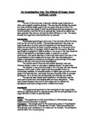
13. The shape of the F-15 is not unlike that of the F-14, it has no orthodox fuselage. It consists of a cockpit nacelle, two engine pods trailing rearward and twin vertical fins. The area between the engine pods is known as the ‘pancake’ it produces lift and acts like a third low aspect wing. This results in a total lift area some 30% greater than the wing area itself. This allows greater handling at lower speeds and reduces wing loading to lower than published figures, which also enhances the high AoA capability of the F-15.
Figure 10. F-15 underbody shape ‘pancake’
Tapered Wing.
14. For an untapered rectangular wing, most of the trailing edge vortices are shed near the tips resulting in the greatest downwash appearing at the tips. If a tapered wing is used, the trailing vortices are produced more evenly along the span and therefore the downwash will also be evenly distributed along the span. Theoretical analysis shows that for a given amount of lift, the smallest amount of vortex induced drag will occur when the downwash is constant along the span. The ideal wing for this application is the elliptical wing as seen on the Spitfire.
This design of wing possesses many inherent manufacturing and structural implications and so the tapered wing was designed and used to meet much of the requirements while remaining structurally strong. The wings also taper in thickness from a thickness / chord ratio of 6.6% at the root to 3% at the tip. This helps to reduce structural weight but also improves the buffet boundary.
Wing Control Surfaces
15. The F-15 has no moveable leading edge devices, the leading edge has however been modified by increasing the curvature of the wing towards the tip. In addition inner trailing edge flaps of the plain trailing edge type are fitted, these augment lift during take-off and allow for slower approach speeds during landing and provide greater handling during slow speed manoeuvres. Unusually for a modern fighter the F-15 is fitted with conventional ailerons, these provide augmentation to the all moving differential tail plane thus enhancing the F-15s role rate.
A C Kermode, Mechanics of Flight (Eighth
Figure 11. F-15 Wing curvature toward tip
Speed Brake.
16. All aircraft need some method of reducing their speed. As they have no contact with any fixed surface such as the ground, they necessitate a wind resistance brake. The F-15 makes use of a large spine mounted dorsal airbrake; this can be deployed during flight to wash off speed, as airbrakes go it is rather large with an area totaling 31.5 square feet. It can be deployed during flight with no adverse effect upon the aircraft pitching moment.
Figure 12. F-15 speed brake deployed
Empennage
17. The tail of an F-15 is not that different from that of the Grumman F-14, however when viewed from the rear it can clearly be seen that unlike the F-14, the F-15 engine nozzles are considerable closer together. This factor alone helps to eliminate the large amount of yaw induced if an engine should fail in flight. Despite this factor should an engine fail in flight a yawing moment would still be present, to combat this yaw effect, particularly at high Mach numbers a twin fin system is used, swept back at an angle of 37o. The fins are raked back to enhance high-speed performance and reduce drag and are canted slightly outwards by as can be seen from the front view to aid manoeuvrability. As the aircraft angle of attack increases, the turbulence behind the body will increase. At very high angles of attack, vertical fins would become ineffective along their entire length; the F-15 fins are canted outwards so that the upper sections of the fins will remain in clear air for a longer period. The rudders on each fin have a large area and chord in relation to their fin; this helps control during the transonic region. Although the twin fins have a large affective area, their moment arm from the centre line of the aircraft is much less than that of a single fin. This will result in less torque being transmitted through the airframe and therefore a lighter airframe. Twin fins also gives much improved ‘Dutch’ roll characteristics and offers rudder control redundancy, useful for a combat aircraft.
Horizontal Tail Plane.
18. The horizontal tail surfaces are fully independently powered and provide roll control, augmented by the ailerons when used differentially and when used together provide pitch control. The tail surfaces are swept back at an angle of 50o and have a saw-tooth leading edge. The saw-tooth leading edge generates a strong leading edge vortex whose flow at high angles of attack is intended to re-energise the outer area of the wing flow, which would normally separate. In comparison to other twin engine combat aircraft, the size of the tail planes appears smaller. This is as a result of the wing design and the podded engine configuration producing so much lateral stability the tail plane was designed mainly for control purposes only. The role of the F-15 implies that high manoeuvrability at high angles of attack will be necessary. To meet this requirement the tail plane is mounted below the wings, this ensures that the tail plane meets clean air at high angles of attack not turbulence from a wing, and avoids deep stall, it also helps to insure against nose up pitching moments at transonic speeds. The ‘beaver tail’ as it is known is the solution to bridging the gap between the engine whilst inducing minimum drag and maximum rigidity.
Figure 13. Rear view of F-15 Tail plane
Figure 14. Horizontal tail planes & ‘Beaver Tail’
Fuselage
19. As mentioned earlier, the F-15 does not have an orthodox fuselage. It does however have a very streamline fuselage mostly due to being designed and built with the area rule in mind. High-speed aircraft suffer from drag in many forms. One way of reducing this drag is to design the cross section of the aircraft to produce minimum wave drag due to volume and diameter. This ideal shape is known as a Sears-Hack body. In order to achieve this body shape the cross sectional area of an aircraft’s body and wings must be adjusted throughout its length to achieve the minimum drag shape. This smooth variation of cross sectional area with length is the basic area rule. When viewed from the front, the F-15 has its engine air intakes close together with their cross section expanding towards the engine. This seems like an odd design but, in conjunction with the cockpit nacelle and the gradually tapered rear of the aircraft, this proves to be a very good solution to the area rule problem. This aircraft has an advantage over most others in that it does not have a main fuselage and the area rear of the cockpit is largely wing area, reducing the problems of the wing / fuselage interface. This incurs minimum wave drag at transonic speeds and so allows quicker acceleration and better fuel consumption resulting in a longer range or time on target. It can also be seen from the front view that the aircraft appears to have a slight dihedral / anhederal effect.
Cockpit
20. The cockpit on the F-15 has been designed to give the pilot a good all round view. At the time of its development the F-15 was aimed toward being a class leader in this department. The handicap incurred with having a high visibility cockpit is that shock waves can form at the apex during transonic flight causing wave drag. The F-15 cockpit has therefore been designed with the area rule in mind and a compromise has been reached between high visibility and reduced wave drag.
Drag Reduction.
21. On any aircraft the reduction of drag in any form has obvious benefits. For aircraft passing through the transonic region, the extra problem of wave drag induced by the formation of shock waves poses bigger problems. As discussed earlier the aircraft is designed using an area-ruled fuselage / wing section, the wing shape being designed to give the lowest drag possible. Another area on high-speed aircraft prone to creating shockwaves is the tail fin / fuselage interface. This problem is addressed on the F-15 by having a smooth transition between fuselage and wing delaying the onset of the shock wave.
The F-15 uses afterburning/reheat to augment its thrust. This method of thrust augmentation requires an expanding exhaust nozzle and these can be a large drag-inducing factor at high speed. The engines in the F-15 have an ‘iris’ exhaust nozzle, which minimises the exhaust cross sectional area in all nozzle positions in comparison to other methods of nozzle area adjustment.
LOCKHEED C-5 GALAXY
17. This aircraft was first seen in1968 and was the new American strategic freighter aircraft. Even today it still remains one of the largest and heaviest aircraft in the world. It soon became a symbol of the American dream. In support of the last phases of the war in South East Asia, the C-5 was quick to prove its value by air lifting items that would otherwise have had to have been brought by sea. Galaxies carried loads totalling 748,000 kg in just ten flights, remaining on the ground for just 32 minutes to off load tanks and helicopters whilst its engines were kept running.
Figure 16. C-5 Galaxy
As this aircraft was developed and used during the cold war, detailed technical information is hard to find, I have been able to obtain some scant information whilst making further analyse from some basic aerodynamic deductions based on the information and photographs available.
18. Wings. The wings are obviously of crucial importance on any aircraft but the role of that aircraft will determine the design of the wing. In the following paragraphs I have studied the wing form of the C-5 Galaxy and tried to determine why the wing was designed in this way.
a. High Wing. The high wing configuration for this aircraft will be a design compromise. This configuration is naturally stable in roll and so will be easier to handle over long sorties. The high wing also provides the ability to mount the turbo fan engines on the wing, granting sufficient ground clearance for ruff strip landings and anti-foreign object damage measures. In conflict with the choice of high wing is the mounting of undercarriage. With a low wing the undercarriage can be retracted into the wing, creating a streamlined shape. With a high wing the undercarriage must be mounted on the fuselage and to avoid restricting cargo space, they are mounted in large nacelles attached to the fuselage. These nacelles will impose a significant amount of drag. Another benefit of a high wing configuration such as this is that the lifting area of the wing for a given span is greater than that of a low or mid-mounted wing.
b. High Aspect Ratio. This aircraft has a very large wing span (67.88 m) each wing being tapered, with a chord length of 13.85 m at root to 4.67 m at wing tip. The resultant reduction in chord length over the span gives the C-5 a high aspect ratio of 7.75. This is very beneficial in reducing trailing vortex (induced) and surface friction drag. It also makes the aircraft very stable in roll.
c. Tapered Wing. The most efficient production of lift comes from an elliptical plan form wing. This form will encourage trailing vortices to form evenly along the span, reducing induced drag. Due to structural and manufacturing problems, the elliptical wing is rarely used. The C-5 arrives at a compromise by using tapered wings. This ensures lift forces are concentrated towards the inboard of the wing, thus reducing large bending moments, particularly on such a large wing span.
d. Anhederal Wings. From the front view it can be seen that the C-5 has anhederal wings, at quarter chord the anhederal effect is the inboard wing sections having a slightly greater incidence than the inboard sections of. The wing is swept to an angle of at quarter chord, this as previously mentioned will help reduce MCRIT. This static configuration alters in flight and when flying at maximum weight, the wings will be level. If the aircraft were designed to have the wings level when static on the ground, during flight the aircraft would adopt a dihedral configuration with undesirable excess stability. The inboard sections will not deflect upwards with lift as far as the outboard sections because of the weight of the engines, for this reason the outboard wing sections have a greater anhederal deflection at rest so that at cruise speed the wing is horizontal across its span. At lower speeds, the anhederal wing allows better maneuverability and control.
Figure 17. C-5 Anhederal wings
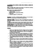
f. Wing Loading. From the equation for lift:, I can rearrange to get an equation for the lift coefficient CL: . This gives CL as a product of air density, aircraft velocity and weight over wing area. Optimum performance will be attained if an aircraft flies at max CL. This will give the best efficiency in terms of Lift / Drag. During a flight the aircraft will use up fuel, reducing its all up weight. This will result in the effective wing loading reducing in value and therefore the CL value will reduce. To avoid this reduction in CL, either V or ρ must be reduced, since reducing V is not a practical solution, reducing ρ by flying at ever increasing altitude will maintain a constant value for CL. Most airliners tend to follow a step-climb profile as their fuel weight reduces.
Another option is to increase the second bracket of the equation. W/S is also known as the wing loading. From the data in fig 15 the wing loading can be calculated by max take off weight divided by the wing area giving a wing loading of 659 kg/m2. At its time of production the C-5 Galaxy wing loading exceeded that of any other transport aircraft and is now comparable to a Boeing 747-400. In figure 17 below, the effect of flying at altitude or having a high wing loading is shown. It shows that for the higher wing loading enables an aircraft to fly faster with little penalty in terms of increasing drag. One draw back of this enhanced higher speed efficiency is that it results in a higher minimum flying speed. A compromise must be met between cruise, landing and take-off performance.
g. Control Surfaces. As the C-5 is a relatively slow aircraft, it is controlled in the conventional manner. It has elevators for pitch control and ailerons and rudder for lateral control. The aircraft has very large trailing edge Fowler flaps to assist low speed manoeuvres in conjunction with sealed inboard slats and slotted outboard slats on the leading edge. In addition the tail plane is of variable incidence. Spoilers are fitted just forward of the flaps to augment role and to act as lift dump devices to assist in short landing distances.
Figure 17. C-5 Galaxy Wing and control surfaces.
19. Wing / Fuselage Interface. The high wing on this aircraft provides a very good blend with the fuselage on the upper surface. The underside of the wing joins the fuselage in a rather perpendicular manner. This will have a large interference drag penalty and there appears to be no attempt to reduce this. Creating a smoother interface would reduce this drag and increase efficiency, however, it may have been decided that the extra fuselage cross-sectional area would induce to much form drag to make this viable.
21. Empennage. The C-5 has a distinctive high T- tail which has been designed to combat many problems. The main points of the tail unit are discussed below.
a. Fuselage Shape. When designing a freighter aircraft, one very important consideration is the shape of the fuselage, particularly the rear end. When an object moves through air it will induce a trailing vortex of low pressure, this causes normal pressure or form drag. Adopting a streamlined shape can reduce this form drag but on freighter aircraft this is not easy. The C-5 attempts to reduce form drag by using a very long rear-loading ramp set at a gradual slope. This prevents a sharp taper in the fuselage cross section and reduced turbulence.
This configuration does however come at the cost of severely weakening the structural strength of the rear fuselage and so will require a stronger structure to support it. At the extreme aft of the airframe directly below the fin the fuselage tapers vertically to a point. From the plan view you can see that this section has no lateral taper apart from a convex section rear of the elevators, this will again help to reduce drag by minimising the induced vortex.
b. Vertical Fin. This aircraft uses a single vertical fin for directional stability. This configuration was probably chosen to reduce flex loads in the thinner rear fuselage, whilst still offering a large surface area for static stability in yaw. A two section rudder is hydraulically power and has no trim tabs. Unfortunately such a high tail calls for a very high hanger roof.
c. Horizontal Tail. The large tail plane of this aircraft sits high above the line of the main wings during flight. Its positioning will have been a compromise between keeping the aircraft height to a minimum and also ensuring that the tail was presented with clean air to provide a good nose down pitching moment. The horizontal tail is of the variable incidence type. It has elevators split into four sections with no trim tabs.
Figure 18. C-5 Galaxy High Tail Plane
22. Static Stability. The C-5 Galaxy is designed as a heavy freighter. For this reason it is desirable for the aircraft to possess good static stability. The aircraft design ensures this in a number of ways:
a. Centre of Gravity. The position of the centre of gravity on an aircraft will greatly affect its longitudinal stability. The design of the C-5 ensures that the majority of loads are carried forward of the aerodynamic centre. This will create a nose down pitching moment to be counteracted by the tail producing a down force to bring the nose up. With the tail producing a down force, the overall lift is reduced and trim drag in induced by the deflection of trim tabs or elevators. This aircraft reduces the problem of trim drag through the length of the moment arm, centre of gravity to centre of tail lift; this is termed the tail volume. This will reduce trim drag by reducing the amount of deflection necessary to enable trim. The trim drag can also be reduced by careful loading to achieve a centre of gravity moved slightly rearwards to the neutral point. At this point the aircraft is longitudinally statically stable and will require little trim; however, as the sortie continues fuel usage will alter the centre of gravity so the load must be set in a compromised location.
b. Wing Mounted Engines. The high engines on this aircraft will contribute a nose down pitching moment due to their thrust line being above the centre of gravity. This moment is counteracted by the high tail plane being even further from the centre of gravity, the drag force caused by the tail plane coupled with the moment arm will counter the nose down moment and keep the aircraft level.
c. Large Tail plane. This aircraft has a huge horizontal tail plane (89.73m2). At cruising speed this will provide the force needed to maintain longitudinal stability and damp out any pitching oscillations.
d. High Wing. As discussed earlier, the high wing position on this aircraft will give inherent roll stability. As the aircraft rolls and goes into sideslip, the lower wing will generate a greater lift due to increased effective angle of attack and also pressure will build up under the wing. The high wing has its angle of attack reduced and as a result of sideslip, a reduced pressure under it. The inevitable result is that the aircraft will roll level. The high wings on this aircraft demonstrate such good roll stability that dihedral wings are not necessary; the aircraft has an anhederal wing at low speeds in order to improve its low speed manoeuvrability.
e. High Aspect Ratio. The high aspect ratio of this aircraft’s wings (7.75) will enhance roll stability in a similar fashion to the high wing. As the aircraft rolls, the lower wing tip will have a greatly increased roll speed due to its distance from the axis. This will result in a much greater effective angle of attack creating greater lift. The higher wing tip will suffer the opposite effect reducing its lift.
24. Conclusion. From my research towards this report I have discovered that analysis of the basic aerodynamic design features of an aircraft is a vast topic. In this report I have concentrated on the basic and fundamental design features of each aircraft. The F-15 was an interesting aircraft to investigate as it operates and in some cases exceed many fixed wing aircraft performance figures at high speeds. The wing geometry design of this aircraft is the key to its flexibility allowing very good low speed handling characteristics combined with high supersonic efficiency and manoeuvrability. Working alongside the wing geometry is the unconventional fuselage layout. This provides a significant amount of lift, even when the wings have stalled, enabling this aircraft to perform some manoeuvres impossible for a fixed wing aircraft with a normal fuselage. The twin outward canted vertical fins are an important requirement in this configuration to ensure that directional stability is maintained at all reasonable attitudes and at very high angles of attack. Conversely, the Lockheed C-5 Galaxy is designed for medium speed steady flight transporting heavy loads. For this reason it is built with a high degree of inherent static stability, so high in fact that the wings are manufactured to produce an anhederal effect at rest and low speeds. This ensures that during take off and landing, the aircraft is not so stable as to be unresponsive at these critical stages. During normal flight and at full load, the wings deflect up to become horizontal enhancing in-flight roll stability but not so much as to detract from control.
Bibliography
Klaus Huenecke, Modern Combat Aircraft Design. Airlife Publishing (1987)
Ray Whitford, Design For Air Combat. Janes (1989)
Ray Whitford, Fundamentals of Aircraft Design. Airlife Publishing 2000
R.H. Barnard and D.R. Philpott, Aircraft Flight. Longman Ltd (1997)
Janes Defence, 1979-1980 Year Book. Janes (1980)
WH Smith, International Encyclopaedia of Aircraft. WH Smith Publishing (1991)