EXPERIMENT
The rotary potentiometer would measure the potential difference across the circuit. Such that for every increase in angle of rotation there is a corresponding increase in voltage. The axle of the rotary potentiometer would have a laser pointer attached to it such that its focus would be positioned on the top of the building from a certain distance perpendicular to the structure (usually a building or pole). Thus the change in angle in order to achieve this would indicate the height.
CIRCUIT DIAGRAM
SCIENTIFIC THEORY BEHIND THE IDEA
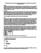
When the adjacent distance is known the height of the opposite side in a right-angled triangle is given by:
TAN θ * ADJACENT=OPPOSITE
OPPOSITE
ADJACENT
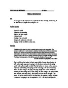
SIDE VIEW OF THE SENSOR
LASER ROTATED (MAX 90 °) IN THIS
DIRECTION TO POINT TO TOP OF BUILDING.
LASER POINTER
WOODEN HOLDER ATTACHED TO AXLE
ROTARY POTENTIOMETER
SPIRIT GAUGE
The height has to be measured from a distance perpendicular to the building and with minimum elevation therefore the sensor is placed at ground level at 10m as and the axle of the rotary potentiometer turned through an angle so that the focus of the laser would be at the top of the building.
Hence a change in voltage is indicated on the voltmeter.
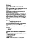
FOCUS OF LASER AT TOP OF BUILDING
SENSOR
In the first trial I used a normal rotary potentiometer from a perpendicular distance of 10m, however the potentiometer proved far too unstable and hence caused inaccuracies. Later the thought occurred to me that a potentiometer with an in built spring would be ideal. To this potentiometer I had to attach the laser pointer, so I had to carve out a wooden holder for the laser pointer to be attached to the potentiometer, this required great determination, skill and dexterity. A diagram of the solution I came up with is shown below.
I then attempted the experiment once more however I encountered a challenging situation, how to tell if the ground was level? At this point a vague recollection of a rustic device in an episode of the Flintstones proved to be a source of inspiration. I decided to use a spirit gauge to ensure that the ground was level.
The third trial I conducted with success. I measured the heights of the windows on six different buildings. I took the readings twice and obtained the following values:
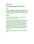
However I was once again face with a challenge, how to obtain values for a sensible range of heights? At first I thought about using a protractor and attaching a cardboard pointer to the sensor to measure the angle, however I realised that this would not be accurate as the pointer in this case would not take in to account the thickness of the laser device nor would it take the horizontal distance from the object into account.. After long hours of contemplation I came up with a logical solution. I would measure out the angles and draw them out on paper ascending vertically. Following this I would put the sensor 10cm away from the scale and proceed to carry out the experiment as normal, only this time according to scale. Following this I would compare the values obtained to those obtained in trial 3.My method for constructing the vertical scale of angles for calibration is shown below:
PAPER 1 PAPER 2
(Vertical scale)
Hence the apparatus was set up as follows:
Paper 2 with scale for SENSOR
calibration.
Using the setup previously described I took the readings four times and obtained the following values:
RESOLUTION
The sensor can only resolve the potential difference to the nearest millivolt, hence the voltage fluctuates for a while when values are not exact but it is easy to get an average from the readings. The values for the height are to the nearest centimetre.
SENSITIVITY
RESPONSE TIME
The response time is almost zero, as response is almost immediate. The only time that can be taken into consideration is the time the user takes to estimate an average when the values are beyond the accuracy level of the sensor.
RANGE AND LIMITATIONS
The calibration of the sensor is such that it is only able to measure heights between 0.87M and 17.32M. This limits its usage to measuring the heights of buildings within this given range. In addition the extent to which the focus of the laser beam can be seen also limits the maximum height of the structure that can be measured. Binoculars may be used but they would not help in some cases for example when attempting to measure the height of a skyscraper, which would be beyond the scope of this sensor.
PERCENTAGE ERROR
The percentage error is 5% as shown in the calculations below:
HEIGHT DERIVED FROM SENSOR=
ACTUAL HEIGHT =
PERCENTAGE ERROR=
HEIGHT DERIVED FROM SENSOR=
ACTUAL HEIGHT =
PERCENTAGE ERROR=
HEIGHT DERIVED FROM SENSOR=
ACTUAL HEIGHT =
PERCENTAGE ERROR=
HEIGHT DERIVED FROM SENSOR=
ACTUAL HEIGHT =
PERCENTAGE ERROR=
HEIGHT DERIVED FROM SENSOR=
ACTUAL HEIGHT =
PERCENTAGE ERROR=
EVALUATION
Improvements that can be made include connecting the rotary potentiometer to a motor that is capable of generating precise movements, and this would be used to change the angle accurately and to hold the axle in position. In addition the horizontal distance could be measured with an ultrasound based measuring device, thus removing the need for using measuring tape, which is to some extent cumbersome.
APPLICATION OF THE SENSOR
Architects, civil engineers, surveyors, safety inspectors, and even football and rugby officials to determine the height of poles, posts, buildings, pillars etc to ensure that they are the correct height would use the sensor in real life. The sensor would enable civil engineers to approximate a cost for a particular structure by measuring the height of the support framework, tell if the height is correct etc., architects to determine if the work on the building is going according to plan, rugby and football officials would be able to determine if the heights of the posts are correct, in addition safety inspectors would find it easy to check if the building’s height has changed which might be an indication of instability of the foundations, earth movements, instability in the structure etc. Those were just a few of the uses for with humans being as creative as they are I am sure many more will be found. It is evident that this device would indeed be a success in the commercial market especially if it were to be tweaked such that it had an ergonomic design, a programmable interface, a graphical display and such like features. The sensor clearly has applications in a vast range of areas in life.