The Q output is left unconnected, as it is not used in my circuit. The set pin is tied low, because I have no need to force Q to 1 and Q to 0, but the reset pin I have connected to a PTM switch (SW2) and a pull-up resistor (R2), as I can then force the Q output to 0, thus resetting my latch until there is another falling edge at the clock input.
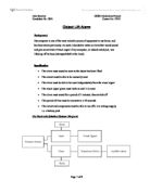
Sub-System Testing
I tested this sub system by checking the voltage at Q using a voltmeter, with input A at different logic levels. When logic level 1 was applied to the input, Q was at 0V. I then changed the logic level at the input to 0, and the output was unchanged, still at 0V. I then rose the logic level at the clock input back up to 1 (a rising edge), and as suspected, the D-Type flip flop triggered on, thus causing the Q output to rise to 4.98V. Then input state was then changed further times, but the output state was unaffected by further rising/falling edges. When switch 2 was pressed and released, the Q output returned to 0V, as the reset pin was made momentarily high.
Visual Signal (Output Sub-System 1)
The visual signal is comprised of an LED (red, labelled D1) with a protective resistor (R2) in series. It is being driven by a transducer driver, as although the D-Type Flip Flop which is producing the signal fed into this output sub-system is itself powered by the PSU, it will not provide enough current to fully power an LED. The LED is rated at 2V, 12mA. Although my circuit is shown here running off of 5V, the finished product will run off of a 6V battery. If the LED draws a current of 12mA, whilst having a voltage of 2V across it, the resistor must have a potential difference of 4V (they add up to Vs, voltages in series add up). The value of the resistor (in Ω) can then be worked out using ohms law; 4V ÷ 0.012A = 333Ω. To make sure the LED is protected adequately, we then use the closest value in the E12 series above the ideal value we just calculated, which is 390Ω. R5 is a protective resistor and limits the current to the base of the transistor.
Sub-System Testing
When the voltage level at input B was 0, the voltage across the LED was 0V, and it was unlit. When the voltage at input B was high (measured at 4.96V) the LED was lit and had 2.12V across it, this could be because of the 5% tolerance of the E12 series.
Timer (Processing Sub-System 2)
This processing sub-system comprises of a 555 timer set up as a monostable (IC2), with a 560KΩ resistor and a 470µF electrolytic capacitor providing the time delay, with the input signal from A (pressure sensor) being passed through a differentiator, before being inverted with a Schmitt Inverter (IC3). This has to be done as monostables are falling edge triggered, and the pulse produced by the input sub-system when the object is lifted off of its base is a rising edge. On a falling edge, the C output will remain close to supply voltage for a time period, which is controlled by the values of R4 and C1. The output C can be ‘reset’ to 0 by returning pins 6 and 7 to logic 1; this is done by instantly charging the capacitor (C1). Switch 4 provides a path with virtually no resistance when pressed, hence the capacitor charges instantly.
The time delay of a monostable can be worked out using the formula:
“Time (s) = 1.1 x resistance (MΩ) x capacitance (µF)”.
This can be used to work out the time delay produced by my monostable when triggered by a falling edge at pin 2:
“1.1 x 0.56MΩ x 470µF = 290 seconds”.
290 seconds is 10 seconds short of 5 minutes, therefore complies with the specification I provided earlier (time delay must be accurate to within ±30 seconds of 5 minutes).
Sub-System Testing
The 555 monostable, when triggered by a brief falling edge from the Schmitt Inverter, produced an average (of 5 tests, which ranged between 327 and 329 seconds) timed output pulse which lasted 328 seconds (and was at 4.97V, according to the voltmeter used). The 328 seconds I timed may have been different from the 290 worked out using the formula for two main reasons; firstly the E12 series of preferred values for gold band resistors has a 5% tolerance range, allowing for a max value of 588KΩ and a min value of 532KΩ. Secondly human error may equate to a proportion of the time difference, depending on reaction time of the individual (in this case, me).
The actual value of R4 I measured at 578 KΩ with an ohmmeter and the capacitance of C1 was measured at 459µF with a capacitance meter.
Audible Alarm (Output Sub-System 2)
This output sub-system consists of a transistor (labelled Q1), its protective resistor (R5), a buzzer (BZ1) and a protective diode (D2).
R6 limits the base current to protect the transistor. The transistor is there to make sure the load can be operated – the 555 monostable cannot supply enough current to power the buzzer.
The buzzer is the component that produces the audible alarm for my circuit, and the diode protects the transistor from large voltages produced by inductive loads (such as a buzzer).
When input C (output from the 555 monostable) turns high (around 4.98V), the voltage at the base of the transistor will be 0.7V, this means the transistor switches on and the collector-emitter voltage is 0, whilst the potential difference across the load is the same as supply voltage.
Sub-System Testing
When tested, the buzzer had 0V across it when the voltage at C was low, but when high the Buzzer had the full 4.98V (supply voltage) across it, and was passing a current of 6.8mA. This caused it to sound whilst C was high (for the duration of the monostable time period, see previous Sub-System Testing section).
Complete Circuit Diagram
Brief Description of How It Works
[NB: for detailed descriptions, see each individual sub-system section]
Switch 1 is closed as the computer (or other object) is placed on top of it. When the object is then lifted off of the switch, the logic level at the clock input of the D-Type Flip Flop (IC1) changes from 0 to 1. As it is rising edge triggered, the Q output takes on the state of the D input, which is latched high – to the supply voltage. This causes the D-Types output to become high, and lights the LED (D1) until the reset switch (SW3) is pressed. The rising edge created as the object is lifted off the switch is passed through a differentiator (or spike producer), and then inverted using the Schmitt (IC3), creating a brief falling edge. This has to be done as otherwise the inverted input will remain low, thus causing the monostable’s output to remain high at the end of its time period, unless another object is placed on Switch 1. This brief falling edge triggers the 555 monostable’s (IC2) output to turn high for the time delay period (set by the values of R4 and C1 – measured at 328 seconds, see separate Sub-System Testing section for greater detail). This in turn causes the voltage at the transistor’s base to equal 0.7, and causes the voltage across the buzzer (BZ1) to equal supply voltage, and the buzzer therefore sounds for either 328 seconds, or until Switch 4 is pressed. Switch 4 provides a path of virtually no resistance when pressed, and hence the capacitor charges instantly, turning pins 6 and 7 to logic 1, and therefore the output to logic 0. The diode is to protect the buzzer from large voltages produced by inductive loads (such as itself).
In short – when an object is lifted off of the pressure sensor (SW1) the LED latches on until it is reset, and the buzzer remains on for approximately 328 seconds or until it is reset.
Circuit Testing
With Switch 1 depressed (i.e. the object on it) its resistance is practically infinite, meaning it has the supply voltage across it (measured at 4.98V). When the object is removed (i.e. stolen) the switch closes, and has virtually no resistance, meaning 4.98V is across the resistor R1. This pulls the clock input of the D-Type flip flop to 4.98V (logic 1) which is the rising edge trigger needed to turn the Q output high (measured at 4.97V). The base of the transistor was now at 0.7V, and was turned on. The LED had a voltage of 2.12V across it and was passing a current of 12mA, which caused it to be fully lit.
The rising edge produced by the input (Switch 1 closing) was then passed through the differentiator and a Schmitt inverter. This caused a very brief falling (from 4.98V to 0V) edge at the pin 2, the input of the 555. Whilst this was so brief it was undetectable by the voltmeter and/or my eyes, I know it occurred as it caused the output (pin 3) of the 555 to turn high, measured at 4.97V, and this only occurs when triggered by a falling edge. The base emitter voltage of the transistor was then 0.7V, which indicates it is conducting. To see whether it was saturated, I then measured the voltage between the collector emitter, and it was 0V, which proves that it was saturated. I then did 5 tests and recorded the length of time it took for the buzzer to stop sounding when not reset, the average being 328 seconds. [NB. The LED did not turn off until reset]. I then triggered the circuit again and tested my reset switches, the LED reset as soon as switch 3 was pressed (the voltage at the reset pin I measured at 4.99V), and the monostable reset after the pressing of switch 4, which instantly charged the capacitor. When pressed, the voltage across it rose to 4.97V, returning pins 6 and 7 to logic 1, therefore returning the output to 0V, and the buzzer stopped sounding. As a further test, I measured the voltage across the collector and emitter legs of the transistor, and found then at to be 4.97V (supply voltage), therefore proving the transistor is off.
Evaluation
My circuit has been tested extensively, and has been found to match all of my specification points.
The alarm does sound as soon as the object has been lifted, any time delay is a fraction of a second and negligible to the human mind.
The circuit can be manually reset, by pressing switch 3 and/or switch 4 (see complete circuit diagram, page 6).
The visual signal can be reset independently, depending on which switch is pressed (3 or 4).
The alarm sounds for a period of time that is accurate to ±30 seconds of 5 minutes, and then switches off. It met its accuracy target in all 5 tests, therefore I believe it satisfactorily meets the specification demands.
The circuit can be run off a low voltage supply, as during testing I was using a 5V supply and the circuit worked perfectly and as it should do.
I therefore believe it meets all demands provided by my specification.
Costed Component List
Acknowledgement of Sources of Information
- List of “Inductive Output Transducers” from Mr. Woolley’s class notes
- Pin out for logic gates obtained from doctronics.co.uk
- E12 series of preferred value resistors found on Wikipedia.org
- Costed component list created in Circuit Wizard, prices from Circuit Wizard’s Rapid Electronics database.
- All circuit diagrams drawn in Circuit Wizard
- Schmitt Inverter IC # found on electronicsinschools.org