interesting.
For the temperature of the wire I would not be able to carry out a fair test because it is extremely
difficult to produce and control the range of temperatures needed without the correct equipment.
If I chose to measure the difference in the resistance in different materials I would chose a number of
different materials and using the same voltage I would record the resistance given by each wire of the
same length and width. Although once again it would be simple to record these results the graphs that
could be drawn would not show any connection between the material and the resistance because of the
limited number of materials I could test with the equipment available.
The final factor is the length of the wire. To measure and record the findings for this factor would be
simple and the results collected could show a connection between the length of the wire and the
resistance given by the wire. This is why I have chosen to investigate this factor.
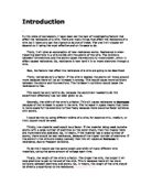
Prediction
I predict that if the length increases then the resistance will also increase in proportion to the length. I
think this because the longer the wire the more atoms and so the more likely the electrons are going to
collide with the atoms. So if the length is doubled the resistance should also double. This is because if
the length is doubled the number of atoms will also double resulting in twice the number of
collisions slowing the electrons down and increasing the resistance. My graph should show that the
length is proportional to the resistance.
The diagrams below show my prediction and should explain it more clearly:
Because the length of the wire is only half the length of the wire below there should be half the number
of collisions between the electrons and the atoms.
The wire below is twice the length of the wire above and so there should be twice the number of atoms
resulting in twice as many collisions and a predicted doubling of the resistance.
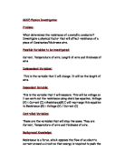
Preliminary Method
In this preliminary experiment I will select a wire that will be used in my main experiment when
investing the connecting between the length of the wire and the resistance of the wire.
To ensure a fair test whilst carrying out my preliminary experiments I am going to be very careful
when selecting my independent variables which are the width of the wire and the wire material. I am
going to use a constant voltage of 2 volts and a constant length of 50 cm.
Apparatus: Meter ruler – To measure the wire being tested to ensure a fair test.
Selection of wires – Different materials and widths but the same length.
Crocodile clips – To connect the wire being investigated to the rest of the circuit.
Voltmeter & Ammeter – To measure the resistance.
Wires – To connect the above items and to complete the circuit.
To measure the resistance of the wire I am going to use the equation RESISTANCE=VOLTS
CURRENT I will obtain the voltage and current readings from the voltmeter and ammeter.
Below is a circuit diagram for my preliminary experiment.
POWER SUPPLY
2 VOLTS
AMMETER
VOLTMETER
CROCODILE CLIPS
WIRE
METER RULER
To ensure a fair test I shall keep the power supply at 2 volts and I shall keep the length of the wire at 50
cm.
Preliminary Results
Below is a table of results which I have collected from my preliminary experiment.
From these results I have chosen to use thin constantin for the wire I am going to use in my main
experiment. I have chosen this wire as it has the highest resistance and so it will be easier to notice any
difference in resistance in my main experiment
Main Method
Before I start my main experiment I have chosen to do a risk assessment which is shown below.
Risk Assessment:
- I will handle the power supply carefully.
- I am going to only use a voltage of 2 volts.
- I will be careful when handling live wires.
Apparatus: Power Supply
Ammeter
Voltmeter
Thin Constantin wire
Meter Ruler
Crocodile Clips
Connecting Wires
I have chosen to use thin constantin wire because from my preliminary results I found that this wire had the highest resistance, because it has the highest resistance it will be easier to measure any change in resistance.
To collect the data for my graph I have chosen to take a range of 5 lengths. I have chosen a range of 5
as to plot an accurate graph I will need at least 5 points to mark on the graph . I have also chosen to
take 3 repeats at each length and then take an average. I have chosen this so that if I have any
anomalous results they will not show when I plot the averages on the graph. The lengths that I have
chosen are as follows : 20cm , 40cm , 60cm , 80cm and 100cm. I have chosen these lengths because
they are easily measured by the meter ruler and give a good range.
Below is a circuit diagram of the circuit I am going to use in my main experiment:
POWER SUPPLY
2 VOLTS
AMMETER
VOLTMETER
CROCODILE CLIPS
WIRE
METER RULER
In my main experiment instead of using an ohmmeter I have chosen to use an ammeter and voltmeter ,
I have done this so that instead of relying on the ohmmeter to give the resistance I will calculate the
resistance of the wire , I shall calculate the resistance of the wire using the equation below.
RESISTANCE = VOLTS
AMPS
I have chosen to use a meter ruler because the lengths that I will be measuring are to big for a smaller
ruler and also the meter ruler can be accurate to +1mm or –1mm.
Results
Below is a results table with the results that I collected from my main experiment.
From these results I have drawn a graph of the length of the wire and the resistance of the wire.
Analysis
From the graph on the previous page I can see that the resistance of the wire is proportional to the
length of the wire. I know this because the Line of Best Fit is a straight line showing that if the length of the wire is increased then the resistance of the wire will also increase.
Conclusion
In my prediction I said that :
“….if the length increases than the resistance will also increase in proportion to the length.”
From my graph I have shown that my prediction was correct as the Line of Best Fit is a straight line proving that the resistance of the wire is proportional to the length of the wire.
The length of the wire affects the resistance of the wire because the number of atoms in the wire increases or decreases as the length of the wire increases or decreases in proportion.
The resistance of a wire depends on the number of collisions the electrons have with the atoms of the material , so if there is a larger number of atoms there will be a larger number of collisions which will increase the resistance of the wire. If a length of a wire contains a certain number of atoms when that length is increased the number of atoms will also increase. This is shown in my diagrams below:
Electron
Atom
In this diagram the wire is half the length of the wire below and so has half the number of atoms , this means that the electrons will collide with the atoms half the amount of times.
Also if the length of the wire was trebled or quadrupled then the resistance would also treble or quadruple.
Evaluation
From my results table and graph I can see that my results that I collected are very reliable. I know this because my results table does not show any individual anomalous results this means that I did not have to leave any results out of my averages because they were anomalous. Also on the graph I can see that none of the averages plotted are anomalous because all the averages lie along the same straight line.
During my experiment I have noticed several modifications I could make to improve on the Investigation if I was to repeat it.
The first of these modifications would be the circuit that I would use. To be more accurate with my results I would use the circuit layout below:
POWER SUPPLY
2 VOLTS
AMMETER
VOLTMETER
WIRE
METER RULER
Instead of connecting the voltmeter to the main circuit I would connect it to the wire which is being tested. I would do this so that the voltmeter is measuring the voltage of just the wire being tested and not the wires of the main circuit as well.
To also improve on my results I would use a digital voltmeter instead of an analogue meter. I would do this because a digital voltmeter is a lot more accurate than an analogue because if the needle in the analogue voltmeter is bent then the readings given off will be false whereas a digital voltmeter does not rely on a needle or any other manual movements.
The next modification I would make would be to use pointers instead of crocodile clips , I would do this because pointers would be more accurate. The pointers would be more accurate because the tips have a much smaller area than the crocodile clips giving a more accurate measurement of the length of wire.
As well as making these modifications I would also improve my Investigation by testing the same wire but different widths of that wire. I would do this to expand on my Investigation.