For copper 0.0173 μ Ω m (1.73× 10⁻⁸ Ω m),
And for aluminium 0.0283 μ Ω m (2.83×10⁻⁸ Ω m)
Conductance and conductivity
Conductance, symbol G, is the reciprocal of resistance and has the unit of the siemens (unit symbol S). Hence
G=1/R
Thus the resistance of 100 Ω is equivalent to a conductance of 0.01S.
Measuring resistance: The resistance of a length of wire is calculated by measuring the current present in the circuit (in series) and the voltage across the wire (in parallel).
There are two common methods ways to measure resistance, there is the Voltmeter-ammeter method way and the Substitution method:
1- Voltmeter-ammeter method: Resistance up to about 50 Ω can be measured using a circuit like this one below
The current through a resistor of an unknown resistance R is set to any convenient value by adjusting the rheostat. R is then calculated using the readings given on the meters:
Figure1 Measurements of the current through a and the p.d. across it, can be
used to find out its resistance.
R= Voltmeter reading
Ammeter reading
For grater accuracy, a range of corresponding voltmeter and ammeter readings can be obtained and a graph of current against p.d. plotted as in figure 2:
The value of x/y gives the unknown resistance R.
The circuit shown above is not suitable for measuring high resistance. If the resistance is high, the current through the resistor is small, and the small current drawn by the voltmeter adds its effect on the reading on the other meter.
For example
Here, the Voltage and current are in proportion.
The resistance has the same value every time. Like all other metals the nichrome obeys Ohm’s law: the resistance of a metal conductor is the same, wherever current is flowing- provided the temperature does not change.
2- Substitution method: resistance of around 100 Ω and upwards can be measured using the circuit in figure 3. X is the resistor of unknown resistance, S is the resistance box containing standard resistor which can be arranged to provide different resistance values by turning the control knobs on the top. X and S are connected into the circuit alternately by moving the connector C between the two positions shown. The value of S is adjusted until the ammeter gives the same reading when the connector is in either position. X and S then have the same resistance.
Resistors
A resistor is a peace of electrical apparatus possessing resistance and selected for use because of that property.
There are many kinds of resistors, but carbon resistors are widely used in electronic circuits. They consist of finely ground carbon particles mixed with a ceramic material, encapsulated into insulated tubes. The casing has a set of coloured stripes denoting the value of the resistance. For more precise values of resistance, wire-wound and film resistors are used.
In the former, a CONSTANT or MANGANIN wire of uniform cross section is wound into a suitable shape; in the latter, a thin uniform layer of resistive material is deposited in a continuous pattern on an insulating core.
As we already know, resistors are mostly used to reduce the current passing through a circuit in some cases, for example there are used in the TV or radio circuits, they keep currents and voltages at the levels needed to make other parts work properly.
But in a variable resistor there is a sliding contact which moves along coil of nichrome wire. By moving the contact, you can change the resistance. Variable resistors like this are used as volume controls in TVs and radios, and also in computer joysticks.
Resistors are identified with a unique symbol as the ones below:
Fixed resistor: or
Variable resistor:
Light dependent resistor:
Thermistor:
Factors effecting resistance
The performance of resistance in a circuit can be affected by many factors; some of these factors are temperature, the thickness of the wire, the amount of voltage, or the length of the wire.
1. The effect of temperature: If the wire is heated up, the atoms in the wire will start to vibrate because of the
increase in energy that has been released as a result. This causes more collisions between the electrons and the atoms as the atoms are moving into the path of the electrons.
When a metal is warmed, its resistance goes up, although not usually by very much. For example, the resistance of a piece of nichrome increases by only 1% for a 100 0C rise in temperature. However, a very large temperature change can have a noticeable effete on resistance
For instance, when a bulb like the one opposite is switched on, the tungsten filament heats up to 3000 0C. At this temperature, its resistance is about double that when cold.
2. Material: The type of material will affect the amount of free electrons which are able to flow through the wire. The number of electrons depends on the amount of atoms electrons in the outer energy shell of the atoms, so if there are more or larger atoms then there must be more electrons available. If the material has a high number of atoms there will be high number of electrons causing a lower resistance because of the increase in the number of electrons. Also if the atoms in the material are closely packed then the electrons will have more frequent collisions and the resistance will increase.
For example:
Nichrome wire has more resistance than copper wire of the same size
3. Wire length: If the length of the wire is increased then the resistance will also increase as the electrons will have a longer distance to travel and so more collisions will occur. Due to this the length increase should be proportional to the resistance increase.
Long wires have more resistance than thin wires.
4. Wire width: If the wire’s width is increased the resistance will decrease. This is because of the increase in the space for the electrons to travel through. Due to this increased space between the atoms there should be fewer collisions.
5. Wire density:
If the wire has a higher density, the resistance will be higher. This is due to the wire having more atoms in a smaller space, creating smaller and less gaps for the electrons to flow through. Because of the increased lack of space there should be more collisions.
Resistors in circuits (Series & Parallel):
Parallel
Involving the simultaneous transfer of the individual parts of a whole.
Circuit elements connected so that the current divides between them and later reunites are said to be in parallel. For resistors of resistance r1, r2, r3 …rn in parallel (Diagram a), the total resistance R is given by:
1/R= 1/r1 + 1/r2 + 1/r3 + …1/rn
Properties of parallel circuits
Branches are formed providing separate paths for the flow of electrons.
Since current branches into separate pathways, a break in one or more of
those pathways do not interrupt the flow in the other paths. (Devices act independently.)
The total equivalent resistance is less than the value of any individual resistor. 1/RT = 1/R1 + 1/R2 + 1/R3 +...
Each device connects the same two points of the circuit; therefore, the voltage is the same across each device.
The amount of current in each branch is inversely proportional to the resistance of the branch.
The total current is equal to the sum of the currents in each branch.
IT = I1 + I2 + I3 +...
Series
Pieces of electrical apparatus are in series when they are connected so that one current flows in turn through each of them. For conductors of resistance r1, r2, r3, …, rn
In series, the total resistance, R is given by:
R= r1+ r2 + r3 + … + rn
b) Resistors in
SERIES
Properties of series circuits
A single path is allowed for electron flow.
A break anywhere along the path stops the electron flow in the entire circuit. (Devices in series act dependently.)
The total resistance in a circuit is equal to the sum of the individual resistances along the current path. RT = R1 + R2 + R3 ...
The current anywhere along the circuit is equal to the voltage supplied
by the source divided by the total resistance of the circuit. (Ohm's Law)
The potential difference, or voltage, is decreased over each resistance.
The sum of the "voltage drops" should be equal to the amount of voltage
Supplied. VT = V1 + V2 + V3 + ...
The voltage drop across each device is proportional to its resistance.
Branches are formed providing separate paths for the flow of electrons.
Since current branches into separate pathways, a break in one or more of
those pathways do not interrupt the flow in the other paths. (Devices act independently.)
The total equivalent resistance is less than the value of any individual resistor. 1/RT = 1/R1 + 1/R2 + 1/R3 +...
Each device connects the same two points of the circuit; therefore, the voltage is the same across each device.
The amount of current in each branch is inversely proportional to the resistance of the branch.
The total current is equal to the sum of the currents in each branch.
IT = I1 + I2 + I3 +...
Resistance of a wire
Planning
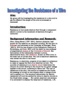
Aim & Hypotheses
This investigation is designed to look into the resistance of different material in the form of wires and their conducting capability in different shapes. In order to do so, the materials are to be tested for their resistance in the shape of wires, and the hypotheses are such that different thickness and length of the wire and the material that makes up the wire itself will affect the electric conduction capability. Hence, the factors are:
- The thickness of the wire.
- The length of the wire.
- The material of the wire.
The experiment will require both the readings of voltage and current in order to produce the value of resistance according to the formula:
R = V (resistance is measured in Ohms)
I
The power supply, however, is varied between 0-12V with 1V interval so that a series of results can be obtained with the single factor altered: a graph of (V) against (I) can be drawn and an average resistance can be produced in this case, rendering it a fairer test. Since each reading does not take long to be obtained, the test can be repeated to obtain a more accurate mean. DC supply is used so that the voltage and current are not fluctuating while a steady reading is needed to be obtained.
Fair Test:
In order for me to obtain the most reliable results, that will be the main base of this project, I must do the following
I must keep the surrounding room temperature the same or the particles in the wire will move faster (if the temperature is increased), this will therefore have an effect on the resistance.
The cross sectional area of the wire must be kept constant throughout the experiment if the wire is damaged as a result of high voltage. Failing to so, this will most defiantly change the structure of the results, because as I have explained earlier that thinner weirs tend to have more resistance than thicker wires.
The material of the wire must also be kept the same as different materials have different conductivity. For example, nichrome wire has more resistance than copper wire of the same length, if we want to look at this from the point of view of chemistry t6his realise on the property of the metal.
The current that we pass through the wire is to be kept the same throughout the experiment, because if this is changed the temperature of the wire will change in a way that is not constant, making the results more meaningless, because you’ll have a huge gap between the figures you obtain.
Prediction:
- An atom consists of a nucleus and orbiting electrons. These electrons can create a flow of current, so the more free electrons there are, the more conducting capability that material has; thus copper is more conductive than iron. Alloys tend to have less free electrons so they will be less conductive. The order of resistance is consequentially copper, iron, constant then nichrome increasingly.
- Wires with wider diameters have more free electrons, because the cross-section surface area is larger in proportion to the length, so the wider the wires are, the less reactive they would be. Resistance is proportional to the cross-section are of the wire given that the length and the material should be the same.
- Longer wires will cause an increase in resistance because the electrons have to travel past more atoms and collisions between the electrons and the atoms are more likely than in shorter wires. Resistance should also be proportional to the length of the wires.
Obtaining evidence
Apparatus
The equipment needed to carry out this experiment consists of:
- A variable DC power pack (0 – 12) V: used to supply the circuit with electricity.
- 4 ordinary wires: used to connect the flow of charge to the crocodile clips, the voltmeter, and the ammeter.
- An ammeter: to measure the current passing through the circuit.
- A voltmeter: to measure the voltage passing through the circuit.
- 2 crocodile clips: to connect the electricity to the wire.
- Assorted wires for test 100m long and 0.4mm in diameter: you may need more than one wire, just in case if the one burns due to high voltage.
- Variable resistor: used to control the current flowing through a circuit.
Method:
The following circuit was constructed to perform the experiment:
Diagram:
Accuracy: to keep this experiment as accurate as possible we need to make sure, firstly, that the length of the wire is measured precisely from the inside edge of the crocodile clips, making sure that the wire is straight when we do this. We must also make sure that the wire is straight when we conduct the experiment. If it is not, short circuits may occur and bends and kinks in the wire may affect the resistance, also. The reading that we take of the voltage should be done fairly promptly after the circuit is connected. This is because as soon as a current is put through the wire it will get hotter and we want to test it when heat is affecting it the least
The two dots () represent the crocodile clips that were placed at the ends of the required length of wire.
1. One metre length of 0.4mm diameter “constantan” (a metal alloy) wire is fixed to a metre rule.
2. The first crocodile clip is clipped to the wire at the 0cm position on the metre rule.
3. The second crocodile clip is clipped to the relevant position depending on the required length of wire.
4. The power supply is turned on to 4 V.
5. The voltage and current are then read off the ammeter and voltmeter, and recorded.
6. The power supply is then turned off and the second crocodile clip is moved to the next position (10 cm every reading).
7. Repeat the experiment once again, to obtain two sets of data, this is because the more data we have the more reliable it becomes,
Safety precautions:
- Make sure that the circuit is properly connected before turning on the power supply, and do not touch the apparatus, especially the tested, naked wires until the power is switched off.
- If the wire you are using melts, the changing of another testing wire should only occur when the power supply if turned off.
- Do not switch on the power pack when there is no resistant wire, and do not turn the power supply too high, because normally laboratory wires may melt.
Background knowledge
Using a circuit such as the one above, an important general relationship can be seen. The variable resistor is used to control the current in the circuit and the voltmeter measures how the potential difference (voltage) across the resistor varies.
Provided that the temperature does not change significantly, the results give a graph that looks like the one opposite, which states that the current is proportional to the p.d.
The relationship is called ohm’s law. Ohm’s law only applies if the temperature is constant, and does not apply to all electrical components.
We can write Ohm’s law in symbols:
V = IR
R is the resistance of the resistor. It can be arranged so the R is the subject, hence:
R = V/I
The larger the resistance, the greater the gradient will be. The gradient of the graph gives the value of resistance.
Ohm’s law does not always apply. A light bulb in place of the resistor in the circuit gives a different pattern for the current and the voltage relationship, as shown in the graph. Here the current and voltage are not proportional. The bulb obviously gets hotter and hotter. Since “resistance” is measured by the gradient of the graph, we have here an example were the resistance is increased.
A heat-dependent resistor or thermistor gives the opposite. Its resistance decreases as the temperature rises.
But obviously we are dealing with “normal” resistors in this investigation, so the gradient of the graph obtained should be the same throughout- in a liner fashion – and the resistance should remain constant as the voltage/current is altered.
Results table
Below are the data and its averages, which I obtained from the experiments. The numbers 1 represents the first experiment & 2 represent the data from the second experiment: (to calculate the average we do exp. 1+2 / 2= average)
To produce a diagram, that will represent the average resistance against the length of the nichrome wire, I need to calculate the average resistance, by using Ohm’s law which states R= V/I
So
R = AV (V)
AV (A)
Analysis
In my prediction, I stated that:
If the length increases than the resistance will also increase in direct proportion to the length.
From my graph on the previous page, I can see that the resistance of the wire is directly proportional to the length of the wire. I know this because the Line of Best Fit is a straight line through the origin showing that if the length of the wire is increased then the resistance of the wire will also increase in proportion to each other. The line of best fit is a straight and it goes though (0,0) if there is no length, there is no resistance proving that the resistance of the wire is directly proportional to the length of the wire. This proves my prediction right.
This indicates that if the length is 20cm, and resistance is 1 Ohm, then if length were to be doubled to 40cm, resistance also doubles to 2 Ohms. I discovered this using the formula
R=Pl/A. As variable P and A were kept constant, the formula can be simplified to R L as predicted.
This is because of the idea, discussed earlier that if you double length, you double the number of atoms in it. As the charges move through the conductor they collide with other atoms. They transfer some of their kinetic energy. This transfer on collision is what causes resistance. So doubling the length doubles the amount of atoms, and so do collisions and resistance.
If the wire is half the length of a certain wire, it would have has half the number of atoms, this means that the electrons will collide with the atoms half the amount of times. In addition, if the length of the wire was trebled or quadrupled, then the resistance would also treble or quadruple. This is indicated on my graph, with the length being 100cm and the resistance being 3.25 Ohms. This in theory would mean that at 50cm there would be a resistance of 1.63 Ohms. From the graph it is easy to tell that the theory is correct and therefore my results reliable. From my results table and graph, I can see that my results that I collected are quite reliable and accurate. I know this because my results table shows a few, individual anomalous results; the anomalous results are at lengths 95cm and 100cm. All the other points are extremely close to the line indicating that my results are accurate.
I think that my results are suitable to confirm my prediction and support a conclusion. I know this because outside resources (Textbooks) say that the length increases in direct proportion to the resistance.
Evaluation
I feel that overall our results were quite accurate. This is can be seen when we look at the graph, which shows a straight line with all of the points being quite close to the line. The one point that was not that close to the line was a slight anomaly, but it was only slight and did not affect the final gradient of the graph. I have found out that for the wire I was using, the resistively at 200C is 4.9 X 10⁻⁷ ohm-meter. From this we can then work out the percentage error of our results:
The accuracy for this experiment is, theoretically, ± 15.7%, but as one can see this does not seem to be the case from looking at the graph. The reason for this could have been due to a number of different factors. Firstly the temperature of the wire was not necessarily 200C when we conducted the experiment and the material of wire may not be as pure as it should have been. The main reason for this was probably due to the equipment that we used being inaccurate. This did not stop us from getting on with the experiment, though, because the equipment would have been out by a constant amount each time therefore there was a constant error.
Most errors in our experiment were encountered in the measuring of the voltage and the ammeter. This is because once again the equipment very old and unreliable. Also I do not feel that the crocodile clips were always fixed securely to the wire with a good connection. This also meant that they were easy to move about on the wire changing the length of it.
Errors rapidly occurred in the setting of the current and the reading of the voltage. Another example of errors is the wire; it was never totally straight when we started the experiment, which may also, as said earlier on, affect the resistance of it.
I do not think that doing any more results in our experiment would have made it any more accurate. I feel that the only way to make it more accurate would be to use different equipment rather than the old manual once we used, I recommend to use digital equipment in the future, so it could make it easier and faster for us to observe the readings of the voltmeter and the ammeter. Or perhaps we could try another method, a method – perhaps were we could use a rheostat in place of the wire, because it is essentially a long coiled wire that is connected at different lengths to change the resistance of the circuit.
In the future if I had another opportunity to do this experiment once again, I would like to do two different types of experiments, one by the laws of Georg ohm and the other on to go by the laws of Gustav Robert kirchoff, the reason for this is because I want to find out the similarities and differences between these two laws, and also I am interested to find out how Gustav Robert Kirchoff’s law applies with modern day electrical properties.
BIBLIOGRAPHY
Theses are the recourse which I used to help me write my introduction:
* T L LOWE BSs, PhD, MI Mgt, J F RIUNCE BSs Calculations for A-level Physics, Third Edition.
(Stanley Thrones Publisher).
*Stephen Pople, New coordinated Science- Physics, 3rd ed.
(Oxford press)
*Stephen Grounds, Edwin Kirby, A-level and AS-level Physic.
(Longman).
*Jim Breithaupt, New Understanding Physics for advanced level 4th ed.
(Nelson thrornes).
*Steve Setford, Pockets Science Facts,
(Dorling Kindersley).
*Jim Breithaupt, 101 key ideas Physics.
(Teach yourself).
*WWW. BBC.CO.UK/ EDUCATION