- Load up ‘Scientific Investigator’ on a computer.
- Set it up so there is an ammeter, voltmeter, and a wire 10cm long, 0.5mm thick and mad of nichrome.
- Record the results from the ammeter and the voltmeter.
- Repeat 2 and 3 but with the wire 10cm longer each time, until you have results for 100cm.
- Repeat 2 to 4 twice more, so you have three sets of different results.
There are no safety precautions to take into account, as it is just a simulation.
Preliminary Prediction: From background knowledge I think that the longer the wire the more resistance there will be. I don’t think that the graph will start to level off and there should be some kind of patter, such as 20cm wire will have twice the resistace as 10cm of wire.
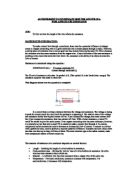
Preliminary Results:
Preliminary Calculations: To calculate resistance, we take V (Voltage) and divide by I (Current) to give the resistance in Ohms Ω.
Prediction: This prediction is much the same as the preliminary one. As the length of the wire increases, the resistance will also increase. Also, for 0cm the resistance should be 0, but I think that it will not work like this as there will always be voltage and current being measured, however I expect it to be less than the 10cm reading.
Equipment:
Ammeter – 0-5 Amperes
Voltmeter – 0-5 Volts
Wires – Insulated
Bare wire – 0.37mm thick, length of 100cm
Power supply – 6 volts
Two Crocodile Clips (labelled X and Y on diagram)
1m Ruler
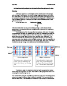
Method/Fair Test: To keep this test fair, we will keep the temperature constant and use the same equipment throughout. Also, we will wait for he voltmeter and ammeter to ‘settle’ and give a fixed result.
- Connect equipment as shown in the diagram above.
- Connect wire Z 100cm down the wire.
- Record Ammeter and Voltmeter readings.
- Repeat 2 and 3, except with Z connected at 90cm, then 80etc… until you reach 0cm and Z is directly touching Y with no bare wire connecting them.
- Repeat 2 to 4 twice more to give three sets of results.
Safety notes: Besides the wire can heat up when it is not insulated, there is nothing that can actually cause any harm. So again, there are no safety notices for this practical.
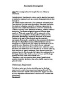
Results:
Calculations: To calculate resistance, we take V (voltage) and divide by I (current)
Conclusion: In conclusion we have found positive correlation between resistance and wire length, as stated in the theory and my prediction. Another point is that the line of best fit does not pass through the origin, which proves that there is resistance even when there is no wire. I believe that this was caused by the rest of the wire going to the voltmeter, or perhaps some other error.
Roughly, the length of the wire divided by ten gives us the resistance. Although this would not work with other variables altering resistance, we would still see similar correlation.