Fair test
To ensure this is a fair test, I have to keep all the factors that would affect my result constant throughout the project. These are the factors that will affect the resistibility of the circuit:
- The diameter and the thickness of the wire
- Temperature
- The material of my wire
To reassure the diameter and the thickness of the wire is the same, I have to use the same wire, which is the wire for the entire experiment. Besides, the apparatus that I begin with should be kept the same to avoid a tiny little difference of the resistance. Temperature is also a crucial factor that should be kept constant. However, it is very hard to maintain the same temperature for each test so I will wait for a minute after I have finish one set of readings in order to cool down the wire. Hopefully this can provide some time for the wire to cool down and remain a similar temperature as the one I do for the first one.
Prediction
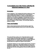
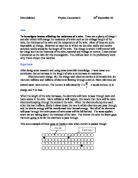
For this investigation, I think if the length of the wire increases, the resistance throughout the circuit will increases as well, as there are more vibrating positive ions in a longer wire which will increase the electron flow. In other word, the distances for the electrons to migrate have increased. The electrons have to move a further distance through the metal. Therefore, the longer the wire, the further the electrons have to travel, and the more likely they are to have collisions with the metal atoms and so the greater the resistance. For example, if the length is doubled in series, the electrons will therefore have twice the resistance of each one separately. Thus the resistance must be directly proportional to the length since when the length is doubled, so is the resistance. It can be represented by the following formulae, R α l. Now, I can say that the length of the wire is proportional to its resistance, and this means if the length of the wire increases, the resistance will increase as well.
The equation of R=V/I can help me to understand that the length of wire is directly proportional to the resistance. After I have obtained eight different resistances, I can then plot a graph of the length of wire against resistance to investigate the relation between these two variables. If a straight line is drawn from the origin of the graph, it proves the length of the wire is directly proportional to the resistance.
The equation of R=pl/A can also prove whether the length of the wire is proportional to the resistance as well. The units are:
R = resistance (Ω)
l = length of wire (cm)
A = Cross section area of the wire (cm2)
ρ = resistance of the material of the wire
In the equation, ρ is the constant of proportionality and will have the units of resistance x length. This constant, ρ, is called the resistivity of the material and from the equation we see that if l = 1 cm and A = 1 cm 2, ρ=R. Therefore, I would say if the length (l) and the area (A) is double, the resistance (R) will be doubled as well. The rho, ρ, will change with temperature and that is why resistance change with temperature. This also shows therefore the resistivity changes depend upon the cross section area and different materials. Mathematically, as long as the resistivity stays the same, the cross section area stays the same as well. This can be represented by the following equation,
R α l.
Results
I have produced eight graphs of current against voltage for the eight lengths as well as a gradient graph. In order to produce an accurate and reliable gradient graph, the results of the eight different lengths are very important because it can directly affect the results. I have used different lengths because it can increase the reliability of the investigation so the data will be more accurate. The gradient graph is the gradient of all best fit lines against the length of wire. I have also checked the diameter of the wire at different lengths by using a micrometer in order to increase its realibility as the diameter of the wire would affects the results if it is not kept constant.
Diameter of wire throughout the investigation:
Analysis
The graphs of different lengths of wire show that if the voltage increases, the current will increase as well. The points that I have plotted on the graph are all close to the best-fit line through the origin. This indicates the graphs of voltage against current are in direct proportion and proves the Ohm’s Law as the law states the current flowing of the conductor is directly proportional to the potential difference across its ends. It can represent by the following formulae, I α V.
To conclude, if the length of the wire increases, the resistance will increase throughout the circuit. This is mainly because when the electrons move through the metal they sometimes collide with the metal atoms and so are slowed down, and this is why resistance is created. Theoretically, if the length of the wire increases, the free electrons have to collide with more metal atoms in which slow down the current, in other word, the resistance will increase.
The length would affect the resistance of an object because the longer the wire, the further the electrons have to travel, and the more likely they are to have collisions with the metal atoms and so the greater the resistance. For example, if the length is doubled in series, the electrons will therefore have twice the resistance of each one separately. Thus the resistance must be directly proportional to the length since when the length is doubled, so is the resistance. It can be represented by the following formulae, R α l.
As a final point, I can now say if the length of the wire increases, the resistance of the circuit will increase as well, and this has proved my prediction that I have stated earlier. This can be shown on my graph resistance against length, as the line is a straight line through the origin. Moreover, every individual length has proved that the Ohm’s Law obeys on them.
Evaluation
In general, I am quite delighted with my investigation, but I think some of the careless mistakes could be avoided in order to improve my results and make it more accurate. There was one anomalous result on the investigation of a 30cm long wire. On the 7th reading, the point on the graph has gone off the best-fit line. This might be possibly caused by the wire was bended when I was investigating. This small change of length might have an effect on the results. Also, the readings from the ammeter and voltmeter are always having of difference of ±0.1, and this might have a small effect on the results. In addition, the electricity supply might be weaker towards the end of the investigation, which may again bring tiny errors on the results. However, apart from that error, I am confident throughout the whole investigation as the points on the graphs are all fit in the pattern of best-fit and is a straight line through the origin.
To improve the experiment, I have to ensure that the lengths of the wire are accurate, and not bended. Using a new piece of wire can do this; nevertheless, keeping the diameter constant is vital as well.
The results that I have obtained are sufficiently reliable to support the conclusion as all the graphs that I have produced are best-fit and through the origin.