Fair Test
To keep the test fair I will keep the current low and same at all time this is so that the rise and variance in temperature is minimal. The wires will be of the same material and have the same diameter. However the length of the wire will be varied so we can see how this affects resistance. To keep this experiment as accurate as possible we need to make sure that the length of the wire is measured exactly from the inside edge of the crocodile clips. We also have to make sure that the wire is straight when we conduct the experiment. If it is not bends and kinks in the wire may affect the resistance. I will take the reading of the voltage as soon as the circuit is connected. This is because as soon as a current is put through the wire will get hotter and we want to test it when heat is affecting it the least, i.e. at the beginning.
Apparatus
- Power Supply: to supply circuit with electricity
- Crocodile clips: to hold wire in place.
- Metre ruler: to measure length of wire (in centimetres)
- Variable resistor: to change current (and keep it the same each time)
- Voltmeter: to measure voltage (in volts)
-
Ammeter: to measure current (in amperes)
- Different Wires (different SWG)
Method
(NOTE: I will be using the following units throughout the experiment.
Resistance – Ohms
Voltage – Volts
Current – Amperes
Length - Centimetres
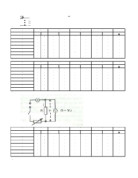
Firstly I will to prepare all my apparatus that I need to start my experiment. Fig 2 shows how I am going to set my circuit. (Note I have not included crocodile clips on the diagram)
Figure 3: The proposed circuit
I will cut exactly one meter of each wire. I will start by taking the reading for 100 cm of wire of each different wire. The length of each wire is then reduced by 20cm. I will take three readings for each wire. The wire which has the most consistent results is the one which I will use to test my hypothesis.
I will attach the crocodile clips to either end of the wire. After doing this I will connect my wire to the voltmeter and ammeter and then switch my power supply on. Then I will record my readings and add them to my results table. As this is preliminary work I will look at my readings and decide which wire is most reliable and constant. I am going to measure the current and Potential Difference across the wire to calculate the resistance. I will use Ohm’s law to do this. Ohms law states that resistance equals voltage divided by current (R = V/I). Where:
V is the Voltage measured in volts
I is the Current measured in amperes
R is the resistance measured in Ohms
I will be using a low voltage on the power supply unit as if it is too high it could damage the voltmeter. I will select the maximum resistance for safety reasons.
Preliminary Work
Table 1: The physical properties of the wires, clearly shows that the constantan wire that has a thickness of 30 SWG is the most reliable and has the most constant results.
Table 1: The physical properties of the wires
Firstly I used Nicrome with a SWG of 30 there were two problems with this wire it was impossible to get a current of o.2 when the length of wire was 100cm. This meant that the result could not be reliable. Also the results for this wire were too erratic so I don’t think that this material of wire will allow me to come to a definite conclusion about the relationship between length of wire and resistance.
The second material I used was constantan with a SWG of 24. This material’s voltage at 100 cm length of wire and 80cm was too similar and at 60 cm it was too dissimilar from the other too. Therefore I do not think that this wire will be of any use to my experiment.
The third material that I used was also constantan but with an SWG of 30. This wire had very good results from my point of view. There was no problem in keeping the current at 0.2 for any length for this wire. As the length decreased at regular intervals so did the voltage. Therefore I have chosen this wire for further study. I will now use this wire to determine for definite whether length of wire affects resistance or not. Another reason why I have chosen the constantan wire is that unlike other wires its resistance is not affected by heat. This will make my results much more reliable.
Now that I have chosen my wire I will repeat the experiment with my chosen wire. I will use lengths of 10cm, 20cm, 30cm, 40cm, 50cm, 60cm, 80cm, 90cm, and 100cm. I will keep the power from the power supply unit at 6v and the current at 0.4. To make sure my overall values are as accurate as possible I will repeat the readings and if the readings are the not the same I will repeat the readings again and then take the mean resistance of the 3 readings.
I found out from other sources such as the internet that the thickness of a wire also affects the resistance of a wire. Therefore I made sure that this factor did not have an affect on my experiment and consequently my results. I did this by using a micrometer screw gauge. I already knew the constantan wire was 30 SWG (standard wire gauge) because it said this on the labelling and my teacher also told me this. However just as a precaution I decided to measure the thickness of the wire at 5 different point of the wire at regular intervals. Making sure that its thickness was constant. Therefore I made the experiment and its results much more reliable.
Actual Experiment
This experiment was conducted using the selected wire; constantan (30 SWG). The power supply was set at 6V throughout the entire process.
In order to avoid any anomalies the experiment was run three times and the following set of results were obtained:
Results 1: The first set of results
Results 2: The second set of results
Results 3: The third set of results
I will now take the mean voltage from the three sets of results so that the resistance can be calculated more accurately. To do this I will add the voltage for each set of results. I will do this for each length of wire therefore:
Voltage for Length 100 for 1st set of results + Voltage for Length 100 for 2nd set of results + Voltage for Length 100 for 3rd set of results.
This equals 10.5. I will then divide 10.5 by 3 to get the mean voltage, which gives 3.5. Finally I will divide this by the current, to get the resistance, which is 0.4.
3.5 divided by 0.4 = 8.75
I have done this for the results for all of the lengths of wire.
Results 4: The mean result of the three runs
Below is a line graph which shows the relationship between the length of a wire and resistance. By looking at the graph it is quite clear that the two have a relationship where if one is increased the other will also increase. However to further prove my prediction I will also do a hand drawn graph which will show much more clearly why I believe that the length of a wire and resistance have a relationship. It will have a line of best fit by looking at which I will know whether resistance and the length of a wire have a relationship.
Figure 4: The graph from my results
The hand drawn graph overleaf shows the line of best fit for the concerned results. The correlation is clearly a positive one. This means that as the length of the wire was increased the resistance also increased. Therefore they have a relationship.
Conclusion
I believe that my result when the length of the wire is 40 cm is anomalous. This is because the rest of the time the resistance increases at 0.75 ohms every 10 cm. On 30 cm it was 2.25 ohms and on 50 cm it was 3.75 ohms. However at 40 cm it went up by 1 ohm where the resistance was 3.25 ohms. This did not affect the 50 cm result which followed the pattern ending up on 3.75 ohms. Therefore I will discount the result for 40 cm. It is very likely that the equipment did not work properly or that I read the voltmeter wrong.
Another thing that proves that the length of a wire and resistance have a relationship is that the resistance was two times greater at 100cm than it was at 50 cm. Meaning that it had doubled exactly. This verifies the fact that the length of a wire and resistance do have a relationship and that the resistance of a wire is directly proportional to its length. In conclusion YES there is a relationship between the length of a wire and resistance.