For the second experiment, I did the same this made my experiment fair. However, I altered the arm, this enabled the arm to rotate more smoothly also I used a larger container for the experiment. Therefore, the float would not constantly hit the sides. In addition, I used a polystyrene float this floated better than a ping-pong ball. All output voltage will be measured in µm on the voltmeter. Also not only as I add a set increasing ml of water must I measure the output voltage I must measure how much the water level for each addition of 100ml of water has increased. Once I have this result I can calculate the average resolution for my sensor
Problems
For the second experiment there where minimal errors, due to the fact the aim of the second experiment was to eliminate errors from the first experiment. For the first experiment, the beaker was the wrong shape for the task. This meant that as the arm was elevated when the water started to fill the beaker the float encountered the sides and therefore giving anomalous results. To stop this from happening in the second experiment I used a larger beaker. This stopped the arm and float from hitting the side. The change in beaker shape would have affected the results for the two experiments; therefore, I used a beaker that gave enough clearance however, it was very similar to the first beaker this meant my results would not be affected by a large amount. I measured this out put voltage difference between the two beakers and compensated for it in the results from my second experiment therefore giving accurate results. Also in the first experiment the rods where joined by using two rods at 90° through the rotary potentiometers spindle. Alternatively, though this measured the level of water accurately, it gave no give in the joint between the two arms, this allowed the float to hit the sides and give me anomalous results. To stop this from happening in the second experiment I used an arm that had been professionally made this meant that it gave accurate results because it would be at a constant angle of 70°, and did not twist or hit the side. The two arms where attached between the 70° angle with two plastic disks these where on a pivot to allow the arms freedom to move from left to right of each other however it would not spin in the opposite direction. This spin would give the anomalous results. For the first experiment, the ping-pong ball also caused problems. When water was added to the container the ball did not rise this was because it had holes in the surface and therefore filled with water. To stop this occurring I changed the ball. In the second experiment, I changed the ball to a polystyrene ball, I did this because polystyrene floats better than a PVC ball, and this gave my results for the second experiment an extra degree of accuracy.
The second experiment also had fewer problems as it was an improved experiment. At first when I set, the second experiment up the potential divider was faulty therefore; I had to change this for a different rotary potential divider. In addition, my first selected beaker for the second experiment also made the float hit the side and gave me faulty readings this meant I had to change for a slightly larger beaker.
Results
Results for the first unmodified experiment;
Resolution 3mm
Results for the second (modified) experiment;
Resolution 2.5mmThese results provide me with the evidence I need to compose graphs and to draw a conclusion.
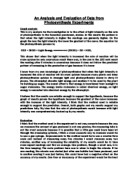
Analysis of my results
The second experiment also had fewer errors as it was an improved experiment. At first when I set, the second experiment up the potential divider was faulty therefore; I had to change this for a different rotary potential divider. In addition, my first selected beaker for the second experiment also made the float hit the side and gave me faulty readings this meant I had to change for a slightly larger beaker and recalculate the difference in volt output per measure meant taken.
The resolution of the second experiment was around about 3mm this was adequate for measuring rainwater as it normal rains more than 3mm in 1 day. However, I increased the resolution of the rainfall detector by 0.5mm. This shows that these small changes have improved my experiment.
The graph for the first experiment is linear, despite this there are some anomalous results for example 900mm, which gave an average volt output, of 0.00079v. This could have been down to a number factor such as parallax error of measuring the water level or taking the reading during a fluctuation of the voltmeter. The results for my second experiment are obviously more accurate when plotted on a graph. This is because on the first graph there are five results that do not fit onto the trend line, however my improved experiments graphical results show that the results are more closely suited to a linear trend line. This is because of the improvements in equipment that was used also more accuracy which means less parallax error. Parallax error is human error of measurement.
Evaluation
The aim of the experiment was to improve an existing experiment to measure the rainfall by using a rotary potentiometer.
The results that I have collected and displayed on the graph show that I have increased the accuracy of the results. The new results form an increased correlation on a trend line. In addition, the resolution of my experiment has increased by 0.5mm of water this is very impressive as I thought at the start of this experiment that the resolution would of remained the same. Also if this was to be made into a really rain measuring gauge it would be easier to keep outside and not have to monitor constantly. This is because of the alterations I have made. Before if the first experiment were left for 24 hours the float would have hit the side if it floated at all, and there would have had to be 3mm of rain for a clear reading to be taken. With the improved experiment, it could now be left outside, because the new arm joint allows the arm movement and to measure at a constant angle however, it will not hit the side of the beaker, only 2.5mm of rain would have to fall for a reading to be taken and the ball is assured to float.
If I was to improve the experiment further, I would use a resistance box, and a power supply that gave a constant 5 volts instead of a power supply that gave a fluctuating 5 volts, I would also use a more sensitive voltmeter. A resistance box would not increase the resolution however; it would increase the strength of the signal to the voltmeter and therefore giving a better reading. If I were to use a fixed 5 volt, power supply it would give me a constant 5 volts instead of fluctuating around 5 volts this would also improve my voltmeter readings and linearity of my graph. If I was to use a more sensitive voltmeter I could increase the accuracy of my results by 1 decimal place this although would not improve my results it would make them easier to anomalies and then I would be able to find a more affective way of stopping the anomalous results.
Bibliography
AS Advancing physics
AS CD rom
www.measure.com