Health and Safety
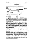
Safety is very important in the experiment as certain objects or procedures can be dangerous and can also affect the results. Nothing was particularly dangerous during the experiment. However, I had to ensure all the equipment was set up properly and all things were clamped or tied together. This involved checking things like the connection between the bob and the string as well as the retort stand. The stand itself was clamped to the desk to ensure it didn't fall over. The bob itself wouldn't be dangerous as long as the method was followed properly by giving it a displacement of 10 degrees.
Fair Testing (Accuracy and precision)
To get an accurate set of results from this experiment it has to be fair. Here are the steps I will take to make the experiment as fair as possible.
Variables
- Length of the string a range of 0.20m to 1.20m (measured at regular 0.1m intervals).
- Time period of the pendulum.
- Size of the bob: The same bob will be used throughout the experiment, so this will remain constant.
- Displacement of the pendulum: This will remain constant at 10 degrees.
- Air resistance: It is assumed that there is no air resistance and 100% of gravitational potential energy is converted to kinetic energy, and vice versa.
-
Gravitational field: This is constant and is being measured in this experiment. The value obtained during the experiment should be 9.81ms-2 to 3 significant figures.
Sources of Error
-
Length of the string: This was measured using a metre ruler. Each measurement is has an absolute error of ±0.5mm as each measurement is given to the nearest mm. This error should be doubled, as there will be an error on each side of the metre ruler.
-
Measurement of time: Human error as well as reaction times can make a large contribution to any errors in the experiment. Readings from digital stopwatches are accurate to the nearest 0.01s but human error means this reading is unlikely to be accurate. I have estimated the total reaction time in starting and stopping the stopwatch is ±0.5s.
-
Size of the displacement: This will remain at 10 degrees. Each measurement has an absolute error of ±0.5 degrees as each measurement is given to the nearest degree.
- Parallax error: Mistakes can be made when making measurements or when choosing the moment start/stop the stopwatch as the bob arrives at the fiducial marker. This can cause errors, especially if the pendulum is swinging quickly.
- Random error: These are associated with nearly all measurements and can never be completely eliminated.
- Take three sets of readings and then take the average of those readings. I will do this to eliminate any anomalous results. If I only take one reading it could be an anomalous result but I won’t know this unless I have more sets of results to compare my data with. Multiple readings ensure that anomalous results are spotted and eliminated.
Results
Conclusion
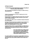
To make my calculation I plotted a graph of T2 (y axis) against length (x axis). This allowed me to calculate 'g'.
T = 2π√l/g it would be more complicated to work out 'g' if T was plotted against length as the graph produced wouldn't be a straight line. By squaring the whole equation you get T2=4π2(l/g) or T2=(4π2/g) x l. Compare this to y=mx+c. By plotting T2 against length the line should pass through the origin (because the c=0) with gradient=4π2/g. By simply rearranging this g = 4π2/gradient.
When plotting the graph most all the points seemed to line up in a straight line that passes through the origin except for the points for the final two lengths (1.10m and 1.20m). I assumed that these were slightly anomalous, the reasons for which I will explain in my evaluation. So I continued the line by ignoring these points. The gradient was calculated using ΔT2/Δl = (4.82-0) / (1.20-0) = 4.01 to 3 significant figures.
Therefore, g = 4π2/gradient = 4π2/4.01 = 9.84ms-2.
Using my results I have calculated g to be 9.84ms-2 correct to 3 significant figures. This value is very close to the accepted value of 9.81ms-2. If the experiment was more sophisticated and errors were reduced it is very likely that I would get a value of 9.81ms-2, although this could be affected by human error in recording or calculation of the results.
Also drawing a T2 graph illustrates that the graph is exponential as it produces a straight line. This also shows that length is directly proportional to T2.
Evaluation
Some assumptions have been made when calculating 'g' using this experiment. Firstly it was assumed that there was no air resistance and that all of the gravitational potential energy in the bob was converted into kinetic energy as it was let go. This could only be true if the experiment had been conducted in a vacuum.
As the pendulum swung some of the energy in the pendulum will have been converted into heat. The proportion of energy converted into heat would have grown as the length of the string increased because the distance travelled by the bob will have increased.
This can be shown by the formula for arc length = rθ with r representing the length (radius) and θ representing the displacement in radians. If r increases so will the arc length (i.e. distance travelled by bob). This assumption may explain the anomalous nature of the results for the lengths of 1.10m and 1.20m. At these greater lengths the amount of energy converted into heat would have been greater due to the greater distance travelled by the bob.
Percentage error in 'g' = Absolute Error / True Value x 100%
= 9.84-9.81 / 9.81 x 100%
= 0.31% (to 3 significant figures)
The percentage error in the result I obtained is very small but it must be noted that I only got this result by eliminating what I thought were anomalous results and in their place assuming that the line I continued by ignoring the two anomalous results was an assumption of what the correct results would have been. By making this change I affected the value for the gradient and the resulting value for 'g'.
A table showing the calculations of the errors in this experiment
Percentage Error = Absolute Error / Value of Quantity x 100%
Percentage Error in Length = 0.001m/Length x 100%
-Absolute Error in Time20 = 0.5 + 0.005 = 0.505s
-Absolute Error in Time2 = ((Absolute Error in Time20/20) x 2) / Value x 100%
Percentage Error in Time2 = Absolute Error in Time2/Length x 100%
Percentage Error in Gradient = Percentage Error in Time2 + Percentage Error in Length
Percentage Error in 'g' = Percentage Error in r2 + Percentage Error in Gradient
= (Percentage Error in Length x 2) + Percentage Error in Gradient
The values for the percentage error in 'g' obviously varies with length but there it is clear that the range in the values of the percentage error of 'g' is very small at 0.07%, which shows the values are consistent. Thus my original calculated percentage error of 0.31% in the value obtained for 'g' seems to fit in well.
The experiment could be improved by either improving the reliability of the existing procedure. Increasing the number of oscillations to further reduce the error caused during the timing could do this.
The value 9.84ms-2 is very close to 9.81ms-2. Considering that the percentage errors in time seem to be the largest I predict that I could further increase the accuracy of the value obtained by eliminating the reaction times.
A more sophisticated experiment would definitely increase the accuracy in the timings. Light gates would remove the error caused by reaction times as they will accurately time the moment the bob passed over the point to complete an oscillation. In the current experiment the fiducial marker was only used as a guide to a complete oscillation. Also using a more rigid pendulum would further reduce the error.
There is a limitation with the graph paper used to calculate the gradient as its gridlines are only spaced in mm. If any measurement required accuracy greater than the value scaled to 1mm then this simply wouldn't be possible. This could be another reason why 'g' wasn't exactly 9.81ms-2.
The effect of air resistance on the pendulum could have been investigated by changing the displacement of the pendulum. I could prove whether my hypothesis about the effect of air resistance on the pendulum was correct by giving the pendulum a greater displacement and repeating the experiment.
HANNAN SHAH