Potential difference is measured in volts (V) by a voltmeter placed in parallel to the energy transfer device, such as a battery, power pack or bulb. 1 volt means that 1 joule of energy is being transferred for each coulomb of charge that flows.
Voltage = Energy ÷ Charge
V = J ÷ C
In series circuits, the total voltage is shared between the various components, meaning the voltages round a series circuit always add up to equal the total voltage of the supply. In parallel circuits, all the components of the circuit receive the same voltage as the power supply.
Now Ohm’s Law shall be looked at. When the voltage applied is doubled, the current is doubled. When the voltage applied is halved, the current is also halved. This isn’t true for all conductors, but it is true for metals and for carbon, if they don’t get too hot. For most circuits, we can use this rule to calculate what will happen when things change. The rule is:
‘For a given conductor at a given temperature the current in it is proportional to the applied voltage’.
This can be written as the formula I = V/R, where R is a constant.
Ohm’s Law applies to metal conductors, but this is the case only if the conductors are kept at a constant temperature. Only then will the current be proportional to the voltage applied. In this case, a graph where current is plotted against voltage will give a straight line. However, if the current heats a metal conductor, the resistance of the conductor will increase. There are however exceptions to Ohm’s Law. This is mainly the case for semiconductors, where the number of particles carrying the current can vary in certain cases. For example, an LDR (light dependent resistor) increases in resistance as the light shining on it decreases in brightness. Diodes only obey Ohm’ Law in one direction, and doesn’t let any current flow in the other direction. And thermistors become less resistant as it becomes more heated, enabling more current to flow through them.
Preliminary Experiment
Previously I have conducted an experiment in order to make a decision on the suitable thickness of wire to be used. There were 2 wire sizes, 28 and 32. In order to decide which wire to use, I recorded the resistance of each wire of 1 metre length. I made use of the power pack as the energy source, 1 voltmeter and 1 ammeter.
Diagram:
Results: Thick wire : Current : 0.65A
Voltage : 2.20V
Resistance : 3.38Ω
Thin wire : Current : 0.32A
Voltage : 2.20V
Resistance : 6.875Ω
Conclusion
In conclusion, this experiment showed that the thin wire provided the largest resistance, due to the fact that there is limited room for the electrons to flow through, resulting in more collisions occurring between electrons and other atoms within the wire, resulting in the atoms of the wire to vibrate more. This then results in the thin wire heating up more than the thick wire, giving the thinner wire a higher resistance than the thick wire.
Fair Test
We need to carry out fair tests in experiments, since by only doing this will we get more reliable and accurate findings. More specifically, fair tests are when we keep the independent variables constant throughout the experiment. The two types of variables are independent and dependent variables. Independent variables are factors that can affect the final outcomes of the experiment. We are also capable in changing these variables, in order to produce the conditions required for the experiment. Dependent variables are the outcomes of the experiment, which we cannot change, but instead are affected by the independent variables.
In our experiment, the independent variables include:
- The voltage across the wire
- The length of the wire
In our experiment, the dependent variables include the final resistance of the wire at different lengths and the current at different lengths. In our experiment, we will change the length of the wire in a controlled way, by reducing the length uniformly, such as by 10cm each time or 20cm each time. The reason for only changing this variable is that by doing this we can easily record how the resistance changes as the length of the wire also changes uniformly, which will produce a definite trend in the readings obtained.
I will keep the voltage constant throughout my experiment, since by doing this I can see how the current and resistance change in respect to the varying length.
I also need to take multiple readings for each length of wire used, since by doing this I can increase the chances of obtaining more accurate readings. By taking multiple readings and finding the average, I will eliminate the possibility of the readings being affected by the inaccurate readings.
How I Will Keep The Variables Constant
Voltage: I will make use of a variable resistor, and by moving the slider up or down with different wire lengths, I can always keep the voltage constant.
Temperature: It is not very simple to control this, but again the variable resistor is needed in order to control this factor. By keeping the voltage fairly low by using the variable resistor, we can also keep the current fairly low, therefore keeping the wire at a fairly low and constant temperature all the time.
Investigation of factors that affect the resistance of a wire
Introduction
In this piece of coursework, I have been set the task of investigating factors that affect the resistance of a wire. There are many things that affect the resistance of a wire but I have only got the chance to do one of these. The one I will choose will depend on it being the most effective and on its ease to do.
Firstly, I will give an explanation of how resistance works. Resistance is when travelling electrons in a wire collide with the atoms of the wire. The collisions between the electrons and the atoms cause the electrons to move slower, which in effect causes resistance. So, resistance is how hard it is to move electrons through a wire.
Now, the factors that affect the resistance of a wire are going to be described.
Firstly, temperature is a factor. If the wire is heated, the atoms will move around more because there will be an increase in energy. This would cause more collisions between the atoms and the electrons. The increase in collisions would cause the resistance to rise.
This would be very hard to do, because the equipment needed to do this experiment effectively has not been given to us.
Secondly, the width of the wire is a factor. This will cause resistance to decrease because of the increase in space in the wire. The increase in space means that there is more space for the electrons to flow freely because there would be fewer collisions with atoms.
I could do this by using different widths of a wire; for example thin, medium, or thick copper could be used.
Thirdly, the material used would be a factor. If the material being used contains atoms with a large number of electrons on the outer shells, then this means there are more electrons available. So, in theory, if the material has a large number of atoms, there should be less resistance, because of the higher number of electrons .If the atoms in the wire are closely packed, then this will cause an increase in resistance, due to frequent collisions.
To do this I would use the same length and width of many different wire materials, using the same amount of voltage each time.
Finally, the length of the wire is a factor. The longer the wire, the longer it will take electrons to get to the end of the wire. This is because there will be more collisions between electrons and atoms. So, in theory, the length of the wire should be directly proportional to the resistance.
This would be very easy to do, and give accurate results. Because of the length being proportional to the resistance, I could link the length of a wire with the resistance of the wire, which would make my graph more interesting.
Due to the effectiveness of this method, I have decided to use the length of the wire as the factor that I am going to use.
Prediction
I predict that, the longer the wire is, the more resistance there will be due to more collisions between the electrons and atoms. The length of the wire should be approximately proportionally the same as the resistance. In theory, if the wire is doubled, then so will the resistance. If the length is twice as much, then there will be twice as much collisions, which would increase the resistance.
Method
Apparatus
· Crocodile clips
· Ammeter
· Voltmeter
· Power supply
· Meter ruler
· Connecting wires
· sticky tape
· Thin Constantine wire
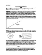
Diagram
The reason I have chose to use Constantine wire is because of its high resistance. This makes it a lot easier to record the results, as it gives me higher numbers to work with.
The resistance is going to be recorded at nine different lengths. I have chosen to record the results at this amount of lengths, as it will give me a much more accurate result at the end of the experiment.
As you can see in the diagram, I have chose to use a digital voltmeter instead of a conventional analogue voltmeter, as this can give me a much more precise result than an analogue meter. This is because the needle on an analogue meter could be bent and give me the wrong reading, but a digital meter does not involve needles, so would give a much clearer reading.
The way to calculate the Resistance relies on this formula:
Resistance = Voltage/current
I will use the Voltmeter provided to get the voltage, and the ammeter provided to get the current (in amps).
Results
Here is a result table from my main experiment:
20 cm
30 cm
40 cm
50 cm
60 cm
70 cm
80 cm
90 cm
100 cm
Average resistance
Conclusion
In conclusion, I have found that my prediction was correct. I said that the resistance will increase approximately proportionally to the length, and as you can see from the graph, this was correct. This is emphasised because the line of best fit is a straight line, which means the resistance is proportional to the length. This proves the fact that the longer the wire is, the more collisions there are between atoms and electrons. So if the wire increases in length, so does the resistance. If the wire decreases in length, so does the resistance. This can be shown in the diagram below:
As you can see in the diagram, the wire on the top is twice as big as the one below it, so it has twice the electrons too.
Evaluation
This experiment has gone satisfactory, but there have been certain things in the experiment that I have not been pleased with.
Some of my results have turned out anomalous. This mainly being:
60cm Anomalous
I have probably ended up with this anomalous result because of an error in recording my results.
However, as you can see from my average resistance graph, the results are roughly on the same line, so this anomalous result did not do much harm when the results are averaged.
I have noticed, now that I have finished my coursework, that there are a number of things I could have done to get more accurate results.
Firstly, I would do the experiment using the width and the material used as a factor too, just to make sure that my averages are as correct as possible.
The next thing I would have done is to use pointers instead of the crocodile clips which I used. This is because pointers are a lot more accurate, because they have a smaller surface area on their tips than crocodile clips. This in effect would give much more accurate measurements.