The first electrical generator was created by Michael Faraday. He hypothesis ed that a changing magnetic field was needed to create an electrical current when using magnetic induction. He tested his hypothesis by wrapping wire around a paper cylinder and attached the ends of the coil to a galvanometer (an instrument for detecting electrical currents). He noticed that when the magnet is moved inside the coil the needle of the galvanometer moved, indicating an electrical current but as soon as the magnet was held still the needle returned to its centre position indicating no electrical current was produced.
Since then we have developed generators which rotate a coil of wire inside a magnet. These generators are not very good for producing large amounts of electricity because floating contacts (contacts that have two parts which can move independently of each other but still maintain a good electrical conductivity) must be used to connect the ends of the coil to the circuit. Floating contacts are very expensive and can not carry a very high current.
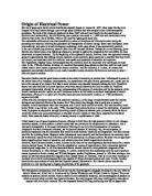
Large scale generators use fixed position coils or staters and a moving electromagnet.
The electromagnet requires a lot less power than is produced in the coils so floating contacts are feasible here. Although the coils are in a fixed position they cannot carry 500MW of electrical power so the coil is broken up in to 3 phases each at 120
degrees rotation to each other.
With phases only 166MW of power is flowing through the wires in each phase.
Transformers
Once generated the electricity must be transmitted to homes, factories and other places that require mains electrical power. This is done using large wires. We know that every conductor has a resistance where useful electrical energy is dissipated in to wasteful heat energy. Most energy is lost when the current is at its highest. To overcome the problem of loosing energy in the wires the current is reduced. To reduce the current and therefore increase the voltage a step up transformer is used.
All transformers have two coils, a primary and a secondary. When an AC current is applied to the primary coil a changing magnetic field is created which is converted back to electrical energy by the secondary coil.
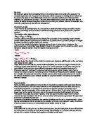
e.g. A simple transformer
In this transformer the ratio of coils primary:secondary is 5:10 or 12. This means that if 20 volts at 1 amp (20Watts) were passed through the primary coil 40 volts and 0.5 amps (20Watts) are induced in the secondary coil assuming the transformer is 100% efficient. Notice that the power in the primary coil is the same as or greater than the power in the secondary coil and there are no other sources of energy, this has to be so to obey the laws of energy conservation.
In industrial transformers many thousands of wire turns are used to make them more efficient, some transformers can be 99% efficient only loosing a small amount of energy to heat and sound. Theses transformers differ greatly from the transformer shown above, the coils are wrapped around each other so more of the magnetic field is collected and converted back to electricity.
At the power station very think cables approximately 20cms in diameter are used to connect the generators to the transformers, this is because very high current is flowing here. At the other side of the transformer the cables on the pylons are significantly thinner than the cables connecting to the generator because less current is flowing.
The national grid uses a voltage of approximately 400kV. On the national grid electricity can travel great distances so the current must be minimal to reduce loss of energy.