Pressure sensor
Specification:
I want my system to have a pressure sensor as an input so when a car rides over it, the output gives a logic 1 signal and triggers the monostable which holds the motor on for 20 seconds.
Circuit Diagram
Instead of using a pressure sensor I used a push to make switch to test it.
To test the pressure sensor I put a voltmeter on either side of the resister.
(To make the pressure sensor on you put the switch on)
Results
When switch opens voltmeter reads 0 V
When switch is pressed voltmeter reads 5.71 V
Evaluation
The pressure sensor subsystem worked as I expected so it can be used for my final system circuit.
Main Switch
Specification
The system will have a main switch that has to be on for the system to work. When switch is closed voltage should be high and when it is open then voltage should be low.
Circuit Diagram
To test the switch I put a LED as an output of the switch.
When switch is pressed LED should light.
When switch is released LED should turn off.
Results
When switch is open: LED is OFF
When switch is closed: LED is ON
Evaluation
The switch works exactly as the specification requires, LED is on when switch is pressed and voltage is also high.
AND Gate
Specification
.
In my system the AND gate will be used so the monostable is only triggered only when both inputs are high, when the voltage in pressure sensor is high and when the main switch is pressed.
Circuit Diagram
1 2 3
Results
AND gate 1: logic 0 LED OFF
AND gate 2: logic 1 LED ON
AND gate 3: logic 0 LED OFF
So the only time the AND gate gives a logic 1 as an output is when both inputs are high.
Evaluation
The AND gate works as the specification requires, the results were as I expected.
When it is connected with a pressure pad and a switch it should give a high voltage output.
When both switches are
Pressed then the LED is
ON
Transducer driver
Specification
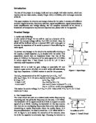
In my circuit there is a transducer driver to give the motor enough current to run. I used a Darlington Pair to power up my motor because one transistor didn’t power up the motor.
Circuit Diagram
Results
When switch is pressed motor operates in a constant speed.
Evaluation
The transducer driver works as required so this is suitable to be used in the final system.
Monostable
Specification
A Monostable will be used in my circuit to hold the motor on for 20 seconds and then turn motor off.
Circuit Diagram
Results
When switch is pressed it triggers the Monostable and holds the LED on for 20 seconds and then turns off.
Evaluation
The Monostable works as required; it holds the LED on for approximately 20 seconds.
Motor
Specification
When both inputs are high in the AND gate, motor should come on.
Circuit Diagram
1 2
Results
Diagram 1 is the circuit I tried first but I had a problem, the motor didn’t get enough current to operate. So I looked through the book called “A Practical Approach To Systems Electronic” and found a solution to this problem, instead of just one transistor I used a Darlington Pair which gave the motor enough current to operate.
Evaluation
The Motor worked as specification required.
FINAL CIRCUIT
When both inputs are high in the And Gate, it triggers the monostable which latches the motor on for 20 seconds and then motor switches off.
The Darlington pair boosts the motor current so it has enough current to operate.
Circuit Diagram
Results
The motor comes on for approximately 20 seconds when both inputs are pressed, and then turns off.
Evaluation
The full system works exactly as expected.
Components cost list:
2 * Push to make switch:
And Gate:
555 Timer:
Darlington Pair:
2 * 10K resister:
820K resister:
47uF Capacitor:
2 * 1K resister:
100 ohm resister:
22 ohm resister:
Motor:
Sources of Information
“A Practical Approach To Systems Electronics”