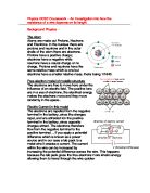
The effect of raised temperature on resistance in this model
Raised temperature on resistance in this model makes positive ions vibrate more, which will then mean more collisions between electrons and positive ions this will also means less gaps between positive ions to pass through. This increased temperature therefore means increased resistance in this model
Potential Difference/Voltage and its effect on current; energy transfer from the power supply to the ions in collisions leading to raised temperature, and hence raised resistance.
An increased voltage in this circuit will mean and increased current, the energy from the lab pack turns to kinetic energy of electrons therefore meaning more vigorous collisions because the gaps between the positive ions have closed down, an increased number of collisions means an increased resistance due to increased temperature. The resistance in a circuit is measured using the formula R= V/I. This means that the resistance is equal to the voltage divided by the current.
Potentional Difference and Current
Potential difference is measured in volts and is measured by a volt metre. While current is
measure in amps or miliamps and measured by
using an ammetre. When we have both of these values we are able to place them into our formula and work out the resistance of a piece of wire, resistance is measured in the unit of ohms (Ω).
Ohms Law
Ohms law states - The current in a metalic conductor at a constant temperature is directly proportional to the potential differnce across it.
Basic Idea
Aim
The aim of this experiment is to investigate how the resistance of a piece of wire depends on its length, as Ohms law states. So in our experiment we will test this theory. Right is the standard test circuit which helps us to find the resistance of a piece of wire R=V/I
Variables
Variables are changing qualities within an experiment; it is any factor or condition that can exist in different amounts. Most experiments have three different types, Controlled, Dependent and Independent.
Controlled Variables:
Controlled variables are the quantities that must be kept the same if the test is to be fair.
Independent Variables
The independent variable is the variable which will be changed throughout the experiment.
Dependent Variable
The dependent variable is that which the person carrying out the experiment focuses their observation as it tells them the differences that the changes of the independent variable have on the experiment.
My Variables –
Independent
Length of the wire - I will be using different lengths of the resistance wire to calculate how different lengths of a wire change the resistance the piece of wire holds.
Controlled
I will use the same type of wire throughout the experiment - I will make sure I use the exact same roll of wire throughout the experiment because different wires have different resistances and I will keep the experiment a fair test.
The thickness of the wire will be kept the same - I will make sure that the wire I use has the same thickness throughout the experiment because the thicker a wire is the more electrical resistance it has, also keeping the wire the same thickness will help to keep this experiment a fair test.
Dependant
I will measure the voltage and the current running through the wire at different lengths – I will measure the voltage in a piece of wire after every 10cm and then work out the resistance, which is the dependent of the variable.
Detailed Procedure
Apparatus
- Uniform wire (length of 1.00m)
- Meter ruler
- Crocodile clips
- Lab pack
- Variable resistor
- Wires
-
Voltmeter (set to measure 0 – 5V)
-
Ammeter (set to measure 0 – 200mA)
Test Circuit Diagram
Method
- The apparatus will be set up in the same format as the diagram above, the voltmeter will be use to measure voltage (V) and the ammeter will be used to measure current(I).
- The wire shall be set to specific values (i.e. 1.0m, 0.9m, 0.8m etc) and will be stretched tight along a meter ruler.
- Once the crocodile clip is set at the selected length along the wire the variable resistor will then be used to change the current readings on the ammeter.
- This experiment is going to be carried out eight times with eight different lengths of wire. Our independent variable is being changed each time here.
- For the first test the crocodile clips will be placed at 0.0m and 1.0m. Then each time the second crocodile clip will going down in interval lengths of 0.10m until 0.3m.
- A reading of current and voltage will be taken at each interval and then repeated to ensure the result is reliable we will measure to the nearest point on the voltmeter and ammeter to increase accuracy.
- These values will later be averaged to get the best results and the resistance will then be worked out by using the resistance calculation, R= V/I.
Safety
- Make sure you keep the electrical current running through the wire at low voltage as this will help to prevent damage to the ammeters and voltmeters.
- Don’t let crocodile clips cross over wires as this could potentially damage the wires.
- Make sure the wire is sellotaped down to prevent the wire causing any damage and giving false readings.
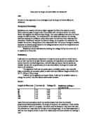
Strategy for results
I will firstly display my results in a results table (shown below) and then I will use these results to create graphs on my findings.
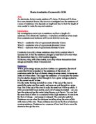
Analyse of Results
The graphs that will be plotted are current (I) against voltage (V) graphs. The current will be on the X-axis and voltage will be on the Y-axis. I will also have a line of best fit on my graph. Below is the way my graphs will be laid out.
Prediction
I predict that all the graphs will all have positive correlation as well as having a clear straight line of best fit going through the origin. I also predict that most of if not all my points will run through the line of best fit, and is a point does not run through the line of best fit, it would be very close. Furthermore I predict that the results will agree with Ohm’s law. It is expected that as you double the length of the wire you double the resistance of it, also it is expected that they should be directly proportional to each other. This is because when you double the length of the wire you double the amount of positive ions in the wire thus meaning that you double the amount of collisions between the free electrons and the positive ions, therefore if there are more collisions one would expect the resistance doubling.
This can be explained as if you take R1 to be 0.2m and R2 to be 0.8m the total resistance will be 1.0m as RT = R1 + R2.