I will control different parts of the experiment in different ways. For one, the material that the wire is made of will be kept the same throughout the experiment so as to ensure a fair test. The cross-sectional area of the wire/ its thickness will also be kept the same. After the preliminary investigation, I chose constantan as the material of the wire (for the reasons explained later in the next paragraph) and chose for the wire to be of the thinnest possible for similar reasons.
As the temperature of a wire increases, the ions vibrate more, making it harder for electrons to pass through and causing more collisions. This therefore means that a higher temperature means a high resistance. We must therefore keep the temperature the same for all parts and repeats of the experiment; it will be kept at room temperature, around 20˚C. The current that passes through a wire describes the number of electrons passing a point in a second, and, the more collisions that the electrons make; the more energy is passed onto the ions causing the temperature to rise and the wire to possibly melt. This therefore means that the wire and thickness that gives the lowest current would be most suitable, i.e. thin constantan. This was backed up by my research during the preliminary investigation which also made me decide that it would be best to use 1 cell of 1.5V to produce the lowest current:
One final decision I made was to use a digital ammeter as opposed to an analogue one. This decision was made on the basis that although the analogue is theoretically more accurate as it is not rounded up, but uses a needle to point out the current, it is hard to read the current to an accuracy of more the one decimal place. Whereas, the digital ammeter is accurate to two decimal places and was therefore the better of the two. The digital voltmeter was also accurate to two decimal places, but we did not did not have a choice to use an analogue type.
I decided to do two repeats of the experiment and then take an average of the figures, so as to get even more accurate results and have the chance to discard any anomalous results. This will especially help when drawing any graphs from my results as it could prove to give a smoother curve, etc.
Circuit Diagram:
Key
Ammeter
Voltmeter
Wire being investigated
Analysis:
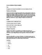
From my graph I can see that as the length of the wire increases, the resistance also increases. There is a strong positive correlation in my data, causing an accurate line of best fit from the relatively accurate points.
The straight line of best fit proves that the resistance is directly proportional to the length of the wire: R α L. This is due to the increase in the length of wire being reflected in the increase of the resistance in that wire, by the same factor. As the number of positive ions in the wire doubles due to the length of wire being doubled (as there is similar density throughout the wire), an electron will make twice as many collisions with these ions whilst attempting to pass through the wire. As the resistance is proportional to the number of collisions, the resistance also doubles.
My line of best fit told me that when the length of wire was 10cm, the resistance was 1.75Ω and that when the wire length doubled (20cm), the resistance also doubled (3.5Ω). This was backed up when the wire length was doubled again (40cm) and the resistance also doubled (7Ω). This information is labelled x, y and z on my graph.
My original prediction was supported by the results that came from the investigation. The line of best fit generally follows my results; most of the points are tight to the line of best fit, however a few deviate from it. My scientific background discussed the expected pattern on the graph and was correct in the theory that the line of best fit would be a straight, diagonal line from the origin (0,0).
Evaluation:
The procedure that I used for my investigation worked very well as it was set up quickly and easily thanks to detail in my planning and my circuit diagram. The only slight problem was that of making sure that the wire did not move at all, even though it was stuck down. Nothing was changed from my original procedure as it seemed to all work to a standard that accurate results could be taken from.
My readings were all quite accurate due to the digital meters that were being used, however they were not exact and I appreciated this. As I did the experiment 3 times in total, an average had to be taken of the six values (3 for voltage and 3 for current), however in the most part the three values had only 0.01 difference in their units. My points on the graph followed a straight line and about 3 out of 15 points lie exactly on the line of best fit. The other points were still very tight to the line and none could be classed as anomalies.
My method worked well as it was not too complicated and the reason for every part’s usage in the experiment had been explained in detail in the procedure. As all our results were accurate, this helped us in plotting a decent graph. The only weakness in the investigation was to do with the constant moving of the wire, possibly leading to some results which are not as accurate as they could have been. More accurate results could have been gained in a number of ways. By using digital volt and ammeters which measure to a higher degree of accuracy, the results would become more accurate as the resistance could have then been calculated with a higher degree of accuracy giving a more accurate graph. If I could have secured the wire in a better way, then the results may have been both slightly more reliable and more accurate as there would be no doubt that I was measuring the voltage and current at exactly the right measurement. Also, if there were a way to perfectly straighten the wire and get rid of twists etc. then the results would have been more reliable as again the length of wire could have been exact as opposed to very near.
My results are very reliable as I used quite precise equipment to measure the variables used to calculate the resistance and form the graph. The results are consistent throughout with no anomalies in the data. When I measured the voltage and current to calculate the resistance, I could have gathered an anomalous result. This would have meant that the resistance would have been calculated wrongly, meaning an anomaly on the graph, not correlating to the same extent as the other calculated resistances. The results are accurate enough to be able to form a firm conclusion as the line of best fit is very close to all of the points and also covers a large range of lengths of wire at medium intervals.
Further work which could mean more exploration into the aim of this investigation could be done using the same procedure as used in this investigation but by changing some values. A greater range of wire could be considered as well as smaller intervals; producing more and more accurate results. Different materials of wire could also be considered as well as different densities/thicknesses. This could be investigated by choosing a selection of wires of the same thickness and putting them into the circuit that was used in this investigation and then measuring voltages and currents at different lengths of wire and forming a resistance from the results. You could then plot a graph showing three lines of best fit, allowing the ability to compare the different materials. This is similar to this investigation as you still measure both the current and voltage to calculate the resistance.
Results: