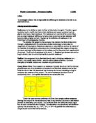
The resistance of a wire is inversely proportional to its cross section width. This means that if the cross section of the wire is doubled, then the resistance will be halved.
Length of wire is another major factor in resistance. Twice the length of wire is equivalent to two equal resistances in series. So therefor if the length of the wire is doubled, the resistance will also be doubled.
The resistance in series circuits is calculated using the equation I know. R= r1 + r2, where R= resistively, r1= hypothetical resistor, r2= hypothetical resistor.
Heat in metal increases resistance, slightly. This is because when the atoms in the wire heat up they vibrate more which makes the atoms get in the way of the electrons more often. The electrons then need to spend more time on deflected courses instead of going straight ahead. This cuts down current slightly.
Different materials have different resistance, and that is the reason why metals have specific purposes in electrical circuits. For example copper is primarily used in electrical circuits because of its low resistance and therefor energy efficient. High resistance metals have their purposes in electrical circuits. Nichrome which is an alloy of 80 % nickel and 20% chromium is often used as a heating element in electrical devices.
The reason some metals have a higher resistance than others is because resistively is caused by the number of free electrons that material has. Therefor if there are more free electrons in a material less energy will be needed.
∙Prediction:
After I had done my preliminary experiment I was able to make a prediction on how the length of a piece of a wire would affect the resistance of the wire in an electrical circuit. I predict that as the length of the wire is increase so is the resistance. So when the length of the wire is doubled then the resistance will also double. So if I had a 30cm wire and a 60cm wire, the 60cm wire would have a resistance twice that of the 30cm wire. Therefore resistance is proportional to length.
∙Measuring/observing:
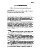
I am going to measure the resistance of different lengths of wire. I will do this by measuring the current and volts that are going through the different lengths of wire. From the background information I found out that you find the resistance of a wire by the simple equation of:
Resistance – voltage/current.
To measure the current and voltage in each wire I will need to use a voltmeter and an ammeter.
∙Apparatus:
* Voltmeter
* Ammeter
* 2 x crocodile clips
* DC power pack
* 2 x 1 meter rulers
* Sellotape
* Connecting wires
∙Experiment Plan / Method:
The experiment is being done to test how different lengths of wire have an effect on the resistance of that wire.
I will need to test different lengths of the same wire. I need to make at least five different changes but from my preliminary experiment I have decided to measure 15 different lengths, to a maximum of 1.50 metres long. There is no range limit of length and in my preliminary experiment I measured 20 different lengths of wire, up to a maximum of 2 metres long. However, it was very difficult to get accurate results because it was difficult to keep such a long piece of wire straight and measure accurately.
The method I will follow to carry out my investigation is exactly the same method as the one I used for my preliminary experiment; everything went smoothly and the results seemed to be accurate in the earlier tests.
1. Sellotape the two metre long rulers onto the bench in a straight line.
2. Connect up the ammeter and voltmeter to the DC power pack.
∙Precaution Taken:
When the length of the wire tested starts to get shorter, problems may start to arise with temperature. As noted earlier, resistance in conductors rises with temperature. This would give inaccurate results.
To try and stop the wire becoming hot, I will introduce a lower current. I found out from my background information that a low current will cause the atoms in the wire not to vibrate as much, so the electrons move more freely and stop heating the wire as much.
In my preliminary practical I found it very hard to measure the exact measurements on the piece of wire being tested as it would always move. I have decided to sellotape the wire to the bench next to the rulers to make it easier to measure.
∙Hypothesis:
I was expecting the resistance to increase in proportion to the length. The resistance should be considerably higher for 1.50 metres than that for 0.10 metres. The reason was explained earlier. Resistances are added together in a series circuit so having a long length of wire will produce the same results as having two half lengths of wire, totalling the same length. Therefore resistance increases with length and also resistance is proportional to length.
Now I am able to carry out the experiment to attain an average; the experiment will be conducted twice for more accurate results.
Results for 1st Experiment
Results for 2nd Experiment
Average of results from 1st and 2nd Experiment
∙Table of Results
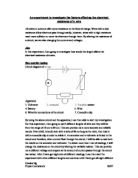
A graph can now be constructed using the information from the table to help me see any relationships or trends in my data. A line of best fit is required for this graph as there are a few points that are not in near perfect correlation. These points are called anomalous.
What is clear is that the level of resistance is increasing as the length of the wire increases. It is also clear that resistance is in proportion to length as the line results are more or less in a straight, ascending line.
The results shown in the graph are as I expected and stated in my prediction. The resistance increases in proportion to length. The level is has increased is stated in the hypothesis. If I look at the table of results, I notice that the resistance has acted exactly as it would if it obeyed Ohm’s Law.
My results are not perfect, most probably due to the limited usability of the equipment provided, but the results are in proportion to length.
The resistance in 10cm of wire should be 50% of the resistance of 20cm of wire; according to my results tables the average resistance of the 10cm length of wire is 2.0 . The average resistance of the 20cm wire is 3.8.
2.0/3.8 = 0.53. This result is very close to 50% and that is significant enough to say that this experiment was a success.
In my prediction I estimated the resistance in 60cm of wire would be double the resistance in 30cm of wire. Now I can see if this statement is correct:
Average resistance of 30cm of wire is 5.4 .
The average resistance of 60cm of wire is 10.1 .
5.4/10.1 = 0.53. 0.53% is close to 50% which shows me that the statement I made in my prediction is correct.
Undoubtedly this experiment proves that resistance increases in proportion to length. The evidence to support this can be clearly seen in the graph. As the length of the wire increases, the resistance also increases.
∙Conclusion
The success of this experiment has been good. The results for the experiment have gone as predicted in the hypothesis and have obeyed all of the previous information that I have collected in my background information. There has been no result from my experiment that has been problematic and could be defied as wrong. Therefor there has been no need to alter the basis of the experiment or question the conclusion given from my results.
The following theory has been proven identifiably by my results.
Resistance is proportional to length. – The results from my experiment undoubtedly prove that resistance increases in proportion to length. The evidence to support this is clearly in my result tables and graph. It obvious to see that length has an affect on the length of wire from the graph because as the length increases, so does the resistance. Also, the graph line is pretty straight indicating that they are in proportion.
∙Evaluation
The accuracy of results can only determine if the investigation was a success or not. If there weren’t any scientific accurate results, the investigation would have been meaningless. I results I have collect are true and I believe to be correct. ‘Correct’ also means as accurate as can possibly be attained. If the experiment needed to be improved there is many way in which this can be done.
One way to improve the accuracy of my results would to repeat the experiment a number of more times, this would enable a true average to be found. When I carried the experiment out I only repeated it once, this is of course more reliable than only conducting the experiment once. Although when the experiment is only repeated once and both experiments differ by a significant margin such as that shown in the result for the resistance when the length of wire is 1.10 meters. If I had a longer period of time to carry my investigation out then the experiment would have been repeated many more times to obtain a more accurate average.
Even if I did repeat the experiment a number of times, the results still wouldn’t be portray as scientifically accuracy. The equipment worked well enough to give an accurate answer but with a few faults. The line on my graph should have been in a straight line, which it isn’t totally. This is due to the few anomalous results. The fault on the line on the graph is a flaw in the experiment and in the investigation. I know his from Ohm’s Law that states
‘Provided that the temperature remains constant, the ratio of potential difference across the ends of a conductor to the current flowing in that conductor will also be constant’
The minor defaults could have been caused by the temperature in the constant but it is doubtful as the voltmeter and ammeter reading were recorded over a space of time of up to 30 seconds to make sure that the reading were not keep on changing and were correct. All the results were taken in the same conditions.
Ammeter readings only have 2 decimal places, therefor could cause a small margin of error, but is only reverent when using extremely low currents for temperature control of the wire. If I did the experiment again I would use a milliammeter, as it would be much more accurate.
Any imperfections in the circuit such as a faulty wire could cause a change in the results. If I had to repeat the experiment I would if possible use new and tested equipment and be able to use the same equipment through out the whole investigation.
The only way I could measure out the lengths of wire was with my hand and ruler. Which isn’t very accurate at all. I length was measured to the best ability but the margin of error was pretty large as the poor method in which the conductor was held in position by crocodile clips. I would need to find a more accurate method of measuring the wire as well as a better method of connecting the conductor.
I believe that any of the minor flaws in results are caused from any of theses points I have just made.
Although there are a few minor errors I have just stated I fill the experiment was very reliable and efficient. It was simple and quick and the results and conclusion are true.
The answer to the original problem is as in the conclusion: as the length of the wire increases so does the resistance of the wire and it is in proportion.
I am pleased with my investigation and have learnt a lot from it. A way I could learn more is to extend my investigation. I could do this is several ways, although I would choose to sill investigate factor that affect the resistance of wire. From my background information I found out length is not the only factor that affects resistance, the cross section width of the wire has an affect on the resistance of the wire as well as using different types of metal as they have different resistance. These would be the factor I would investigate if I had to extend my investigation.
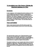
Investigating the cross section width of the wire, I would need to prove that the resistance of a wire is inversely proportional to its diameter. For this experiment to work, one material will be needed, although several different diameters for this wire will also be required. The length of the wire will be kept constant through out the investigation to keep it a fair test. I would carry out the experiment out in the same was as I did when I investigated how length of wire affected resistance, but instead of changing the length in one piece of wire I would change the diameter of several pieces of wire.
If I extended my investigation further I would then investigate what affect it would have on the resistance if I change the material I am using. I would need to do an experiment to prove that different materials have different resistances. To do this I would need to choose tow materials, which conduct electricity, and test them against each other. This would then show me if their resistances were the same or not. From my background information I found out the two best materials to use is copper and nichrome wire. I will have to make sure the wires tested must be exactly the same length because other wise it will not be a fair test. I will find the resistance from 10 cm t0 1meter of wire for both the copper and nichrome wire. I would do this in the same way as I found the resistance for different lengths of wire; apart from instead of just changing the length of one piece of wire I am going to have to change the length for two different pieces of wire.