Cross-sectional area is impractical, as the size of the measurement is so small, the units are too large to measure accurately with.
Temperature is extremely hard to keep constant at a specific point. The rheostat required to keep the temperature constant between 30ºC and 100ºC would have to be enormous. Also, the wire would melt under the current involved, acting as a fuse.
So, I will investigate length.
Prediction
I predict that as the length of the wire increases, the resistance will also increase. I predict that resistance is directly proportional to length (RL)
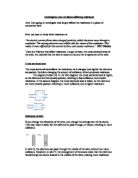
I predict this because resistance is caused by collisions between the flow of electrons and the atoms of the wire. If you increase the length of the wire, you increase the amount of atoms, and therefore the number of collisions.
In Wire X, there are 16 possible atoms to collide with. In Wire Y, there are 32. If the same amount of electrons pass through each wire, each carrying the same amount of charge, the resistance in Y should be larger than that of Wire X.
Say that the energy released by an electron hitting an atom is x.
Say that y electrons pass through both wires, and the electrons collide with every single atom.
Say that the number of atoms is a
Therefore: R = axy
In wire X, R=16xy
In wire Y, R=32xy
The resistance in wire Y is twice that of wire X.
This means that resistance is directly proportional to length, provided the other 3 factors remain constant.
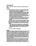
So, if plotted on a graph, I would expect to see:
R
Length
The graph would pass through the origin, as when the length is 0, there is no wire for there to be any resistance, which is logical.
Preliminary experiment
In my preliminary experiment, I set up a circuit with an ammeter, voltmeter, and 5cm of constantan wire. I took measurements of the potential difference of the wire, and the current flowing through it. I then repeated this experiment using the lengths 10, 15, 20, 25, 30, 35 and 40cm.
During the experiment, we kept the wire submerged in a water bath, to prevent melting. However, we had difficulty fitting the larger lengths of wire into the bath. Because of this, during the experiment we will wrap the wire around a pencil, forming a coil.
Our results are slightly anomalous. This could be because the water was also acting as a short circuit, allowing electricity to bypass most of the wire. Due to this, we will use de-ionised water in the bath, which does not conduct electricity.
We also had slight problems with the wire overheating, even with the water bath. Because of this, we will reduce the voltage to 6 volts.
Main Experiment
Circuit Diagram
Equipment required
Power pack set to 6 volts
5 insulated copper wires
2 crocodile clips
An Ammeter
A Voltmeter
5cm, 10cm, 15cm, 20cm, 25cm, 30cm, 35cm and 40cm of constantan wire (non insulated)
A pencil
2000cm³ water bath, containing 1500cm³ of de-ionised water.
Method
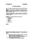
- Complete the circuit as shown in the diagram, using 5cm of constantan wire as the test wire.
- Wrap the 5cm of wire around a pencil, forming a coil.
- Place the coil into the de-ionised water bath
- Check that the power pack is set to 6 volts, and turn on.
- Record the voltage and current, taking the readings off the voltmeter and ammeter respectively. Write this down in a table.
- Turn off the power pack, and remove the constantan wire. Replace it with the next wire, and repeat the above steps.
- When finished, repeat the entire method twice
- When you have done all the tests, disconnect the equipment, making sure iot is dry, and pack away.
Controlling variables
There are several variables that need to be kept constant, for this to be a fair test.
Safety
Electricity is dangerous to humans. Because of this, we will need to take several precautions.
- Lab procedures apply. We will not run, and we will make sure the woking area is free of obstruction
- We will not change the circuit while electricity is passing through it.
- We will not touch the de-ionised water while the circuit is closed. (The water does not conduct electricity, but accidents may occur, so we will make sure there is no chance of electrocution.)
- We will use a power pack with a RCCB, so if electrocution does occur, it will be halted, preventing damage.
Results
Next I will calculate the average current and voltage for each length, and use this to calculate the average resistance
Now I will use Ohm’s law (V=IR) to calculate the resistance. Ohm’s law only applies when the temperature is kept constant, which we have, so we can use it.
V=IR
R=V/I
Conclusion
My graph shows that resistance is directly proportional to length. I know this because my line of best fit is a straight line, with a positive gradient. If I double the length, the resistance is doubled.
Resistance is directly proportional to length because it affects the amount of atoms that the electrons have to avoid. As the length increases, the chances of the electrons colliding with the atoms also increases, therefore there are more collisions, which generates a higher resistance. If you double the length of the wire, there are twice as many atoms to collide with, so the resistance is also doubled. This is shown on the line of best fit. If you look at the resistance at a point along the x axis, say 15cm (1.4Ω), and double that x value, 30cm (2.8Ω), the resistance is also doubled.
These results agree with my prediction, as I said that resistance would be directly proportional to length.
I am going to attempt to find out a formula for working out resistance in terms of length.
Length=l
R L
=>
R=xL x being unknown constant
What could x be?
There are three factors that affect resistance, besides length: Temperature, Resistivity of the metal, cross-sectional area.
Temperature has a positive link to resistance. I do not know whether this is directly proportional, or whether it could produce a quadratic graph. I need to investigate this in a further experiment.
The resistivity of a metal cannot be measured by conventional means, only as a comparative measurement.
Cross-sectional area has an inverse affect on resistance, but I do not know whether it is a linear effect or a quadratic one.
So, the unknown coefficient of L must involve the temperature, resistivity, and cross-sectional area.
This would be a good area for further work. I would have to investigate temperature and cross-sectional area, as resistivity is relative, and cannot be easily measured.
When investigating temperature, I would have to use a wire with low resistance and a high melting point, because it would have to be capable of withstanding high temperatures without melting. Copper should be suitable.
I would conduct the experiment in a similar fashion, except I would have to use an oven instead of a water bath, and heat the wire to the required temperature, and there take a reading. This would require a thermometer, to measure the temperature of the wire.
Cross-sectional area is slightly more difficult to measure. I would suggest, instead of using different thicknesses of wire, to use more wires, thus splitting the current. This would have the same effect as using a wire with twice the area. If you wanted an absolute result, one would have to measure the diameter of the face of the wire, and then use the equation ∏r²=a to work out the area. You could then plot this on a graph.
Evaluation
I believe the experiment was reasonably accurate, but there are several improvements that could be made.
The experiment was conducted with a reasonable degree of accuracy, using ammeters and voltmeters tuned to 2 d.p. This gave us a fairly accurate measurement of the current and voltage in the wire.
However, we have no guarantee that the temperature stayed constant. The water bath reduced the difference in temperature, but there could have been a difference in the temperature, which may have affected the results. I doubt it made a large impact, as we got the results we expected that follow scientific logic.
The power packs used are not the most accurate of power packs, meaning that the e.m.f produced differs from the amount it is set to. They fluctuate in their production of e.m.f, meaning that the results may have been inaccurate. Again, this will have made a negligible impact.
Improvements to the method could be made. Instead of using the power packs we were using, we could use more up-to-date, sophisticated power packs, to avoid fluctuations in the current.
We could refridgerator the water beforehand, resulting in a cooler wire, and a smaller variation in temperature.
The results we got were accurate. We know this because they follow a clear trend, highlighted by the line of best fit. We do not have any radical anomalous results, as they are all close to the line of best fit. The greatest point of inaccuracy is at 25cm, where the value is 0.2Ω away from the line of best fit, which is within our tolerance margin.