The material of the wire must also be kept the same as different materials have different conductivity. The last two factors will be kept the same by using the same wire all of the way through the experiment.
The current that we pass through the wire is to be kept the same, also. If this is changed the temperature of the wire might change in a way that is not constant making the results more confusing.
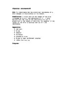
Apparatus:
1. Wire, over 50 cm long
2. Rheostat
3. Power supply
4. Six connecting wires
5. Two crocodile clips
6. Voltmeter
7. Ammeter
Plan:
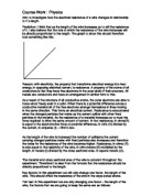
1. Connect circuit as shown in the diagram.
2. Adjust rheostat until the ammeter reads .3 A.
3. Record voltage on voltmeter
4. Repeat the experiment with the following lengths of wire, connected between the two crocodile clips:
- 10 cm
- 15 cm
- 20 cm
- 25 cm
- 30 cm
- 35 cm
- 40 cm
- 45 cm
- 50 cm
5. Use Ohm´s law to find the resistance of the wire, equation (1).
Diagram:
Safety: this is not a very dangerous experiment but despite this you must always handle electricity with care, keep the current low, handle with dry hands etc.
Accuracy: to keep this experiment as accurate as possible we need to make sure, firstly, that the length of the wire is measured precisely from the inside edge of the crocodile clips, making sure that the wire is straight when we do this. We must also make sure that the wire is straight when we conduct the experiment. If it is not, short circuits may occur and bends and kinks in the wire may effect the resistance, also. The reading that we take of the voltage should be done fairly promptly after the circuit is connected. This is because as soon as a current is put through the wire it will get hotter and we want to test it when heat is effecting it the least, i.e. at the beginning.
Preliminary: upon testing to see if the experiment would work I found no problems with the plan I described earlier. I was able to get the following results:
LENGTH
(cm) CURRENT
(A) VOLTAGE
(V) RESISTANCE
(=V/I(Ù))
10 0.3 0.13 0.43
15 0.3 0.20 0.66
20 0.3 0.27 0.90
25 0.3 0.35 1.16
30 0.3 0.42 1.40
35 0.3 0.48 1.60
40 0.3 0.57 1.90
45 0.3 0.60 2.00
50 0.3 0.68 2.26
Observations
Observations: we will observe the reading on the voltmeter change as we change the current to .3 A. we also observe a general increase in the voltage as the length of wire we use gets longer. The rheostat will also be set at different positions for the different lengths of wire that we use.
Ev from essaybank.co.uk idence: to make sure our overall values are as accurate as possible we will repeat our readings 3 times and then take the mean resistance of the 3 readings. We will also be able to spot and discard any anomalies from our results.
Results:
Set (i)
Length
(cm) Current
(A) Voltage
(V) Resistance
(=V/I in Ù)
10 0.3 0.13 0.43
15 0.3 0.20 0.66
20 0.3 0.27 0.90
25 0.3 0.35 1.16
30 0.3 0.41 1.36
35 0.3 0.48 1.60
40 0.3 0.56 1.86
45 0.3 0.62 2.06
50 0.3 0.69 2.30
Set (ii)
Length
(cm) Current
(A) Voltage
(V) Resistance
(=V/I in Ù)
10 0.3 0.13 0.43
15 0.3 0.20 0.66
20 0.3 0.27 0.90
25 0.3 0.35 1.16
30 0.3 0.42 1.40
35 0.3 0.49 1.63
40 0.3 0.57 1.90
45 0.3 0.61 2.03
50 0.3 0.70 2.33
Set (iii)
Length
(cm) Current
(A) Voltage
(V) Resistance
(=V/I in Ù)
10 0.3 0.13 0.43
15 0.3 0.20 0.66
20 0.3 0.28 0.93
25 0.3 0.34 1.13
30 0.3 0.40 1.33
35 0.3 0.48 1.60
40 0.3 0.57 1.90
45 0.3 0.62 2.06
50 0.3 0.70 2.33
Average
Length
(cm) Resistance (Ù)-Set (i) Resistance (Ù)-Set (ii) Resistance (Ù)-Set (iii) Mean Resistance
(Ù)
10 0.43 0.43 0.43 0.43
15 0.66 0.66 0.66 0.66
20 0.90 0.90 0.93 0.91
25 1.16 1.16 1.13 1.15
30 1.36 1.40 1.33 1.38
35 1.60 1.63 1.60 1.61
40 1.86 1.90 1.90 1.89
45 2.06 2.03 2.06 2.05
50 2.30 2.33 2.33 2.32
Anomalies: there was only one real anomaly in this experiment and it has been highlighted like this: 000
Analysis
Trends: from the graph we can see one very clear trend, which is, as the length of the wire increases so does the resistance of it. Another, more significant thing is that it the increase is constant. This is indicating by the fact that the line drawn is a straight one. One may also note that the gradient of the line drawn is (1.85/40) .04625.
Conclusion: I think that from my results I can safely say that my prediction was right. The resistance did change in proportion to the length. This is because as the length of the wire increased the electrons that made up the current, had to travel through more of the fixed particles in the wire causing more collisions and therefore a higher resistance. We can work out what the resistivity of the wire should be from our results using the formula
It is obvious from the formula that R/l is simply the gradient of the graph, therefore
Evaluation
I feel that overall our results were quite accurate. This is can be seen when we look at the graph, which shows a straight line with all of the points apart from one being very close to or on that line. The one point that was not that close to the line was a slight anomaly, but it was only slight and did not effect the final gradient of the graph. I have found out that for the wire I was using, the resistivity at 20©C is 4.9 X 10⁻⁷ ohm-meter. From this we can then work out the percentage error of our results:
The accuracy for this experiment is, theoretically, ± 15.7%, but as one can see this does not seem to be the case from looking at the graph. The reason for this could have been due to a number of different factors. Firstly the temperature of the wire was not necessarily 20©C when we conducted the experiment and the material of wire may not be as pure as it should have been. The main reason for this was probably due to the equipment that we used being inaccurate. This did not stop us from seeing the trend, though, because the equipment would have been out by a constant amount each time therefore there was a constant error. So the trends that were predicted in the plan still were shown.
Most errors in our experiment were encountered in the measuring of the wire. This is because it simply was not very practical to hold a piece of wire straight, whilst holding it next to a ruler and then trying to accurately fix crocodile clips to the right part on the wire. Also I do not feel that the crocodile clips were always fixed securely to the wire with a good connection. This also meant that they were easy to move about on the wire changing the length of it. Errors rarely occurred in the setting of the current and the reading of the voltage. It was just in the preparation area that they did occur. Another example of this is the wire was never totally straight when we started the experiment, which may also, as said earlier on, effect the resistance of it.
I do not think that doing any more results in our experiment would have made it any more accurate. I feel that the only way to make it more accurate would be to use a different method – perhaps were we had a bar that did not bend in place of the wire. We could even use a rheostat in place of the wire, because it is essentially a long coiled wire that is connected at different lengths to change the resistance of the circuit
Introduction
Electric charge on an object is often called static electricity. Objects charge up because they gain or lose electrons. The electron is the smallest part of the atom. The electron carries a fixed negative charge. Every atom has a positively charged nucleus surrounded by electrons. An atom is uncharged because it contains equal amounts of positive and negative charge. Current is a flow of electrons. It is measured in amps. A circuit can be in series or parallel. In a series circuit the parts are placed one after another. If you remove a part the circuit is broken. A parallel is different because the bulbs are placed opposite to each other.
Voltage pushes electrons around the circuit. It is measured in volts. Ammeters are used in series circuits and voltmeters in parallel circuits. To measure the resistance in a circuit you use this formula:
VOLTAGE
CURRENT
These are some factors that may effect my results:
1. The starting and stopping of the stopwatch may not be 100% accurate.
2. The wire may not give an accurate reading due to frequent use.
3. If you do one experiment and then another straight after the warmth of the wire may effect the results.
Method
1. Connect the crocodile clip (that is joined to the volt meter) to the wire at 10 cm and get a reading of amps and volts.
2. Repeat this for 20,30,40,50,60,70,80,90 and 100cm.
3. Rcord the results in a table and plot them onto a graph.
Prediction
I predict that the longer the wire the higher the resistance. This is due to the fact that the electrons in the wire have to travel further. If the from essaybank.co.uk wire is longer the electrons will take longer to push through all of the atoms.
Fair Test
To make my experiment a fair test I will set the experiment up accurately and keep the Power pack charge the same at all times (measured in volts).
Results
Distance (cm) Resistance (ohms)
10 0.25
20 0.46
30 0.65
40 0.87
50 0.04
60 0.28
70 0.49
80 0.62
90 0.85
100 0.04
Conclusion
My prediction was correct, the longer the wire the higher the resistance. This happened because when the wire was shorter the electrons had less to travel and therefore didn’t take as long to give a reading of volts and amps. Also when the wire is shorter the electrons move quicker because they don’t have as many atoms to push themselves through.
Evaluation
To make my experiment more accurate I could have got 3 sets of results and found an average but this would be too time consuming. I don’t think I could improve the experiment because it worked very well and got me some accurate results. I also found the experiment quite easy to set up as well. A further experiment I could do would be to see whether the diameter of a wire effects the resistance. This would be very fascinating because it is similar to the experiment I have done.