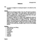
Diagram
Making the Investigation both Safe and Fair
- The power will not be left on too long to get the readings as temperature is also a factor that affects the resistance of a wire and leaving the wire would heat it up and therefore the results would not be accurate.
- The power supply will be set to 6 volts for all the wire lengths so that the only factor that is varying is the length of the wire.
- The same thickness wire will be used for each set of results, until the thickness is changed.
- Results will always be taken at 10 cm intervals on the wire from 100cm to 10cm.
- The voltmeter will always be in parallel with the piece of wire and the ammeter will remain in series with it throughout the investigation so that results can be taken.
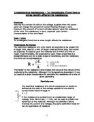
Prediction
I predict that in this experiment the longer the wire is, the more resistance that will be offered. My prediction is backed up by the fact that when the wire is longer, the electricity has to travel further distance and will therefore the electrons will collide with more protons as it passes.
My Prediction is also that the length of the wire will be directly proportional to the resistance of the wire. This relates to the thickness as well as the resistance is linked with how much surface are of the wire there is, so whether it is in the thickness or the length, it is inconsequential. So therefore the thicker wire will have higher resistance readings than the wire with the smaller gauge. Despite the fact that three readings will be taken from each length, the resistance should remain the same each time because both the voltage and current will decrease together.
Preliminary Experiment
To uncover any problems that may have arised in the experiment, we first performed a preliminary experiment, but we performed it and no problems did arise. Hence we continued with our original plans and do not need to make any alterations to our method. We did not record the results for our preliminary experiment as time was a valuable virtue in getting the results that were essential.
GCSE Physics Coursework: Skill O
Factors Affecting the Resistance of a Wire
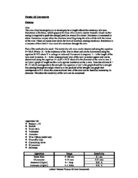
Results for Wire with Standard Gauge 36 (0.193 mm diameter
Results for Wire with Standard Gauge 30 (0.31 mm diameter)
Results for Wire with Standard Gauge 30 (0.31 mm diameter)
GCSE Physics Coursework: Skill A
Factors Affecting the Resistance of a Wire
The line of best fit on the graph passed through practically all the points, without having to curve the line. This straight line shows that the length of the wire is directly proportional to the resistance in the wire, thereby proving that length of the wire is indeed a factor in the resistence of a wire.
If carried on the lines would pass through the origin, as when there is no wire there can be resistance. This further proved that if the length is doubled, so too then should the resistance in the wire, for example when the wire is 20cm if the resistance is 2Ω, then when the length of the wire is doubled, the resistance should also doubled to 4Ω.
I shall now prove this theory with my results to back it up:
When the length of wire was 20cm and the gauge was 30, the resistance was 3.24Ω,
and when this was doubled to 40cm, likewise the resistance doubled to 6.39Ω (ideally it should be 6.48Ω).
Also when the length of wire was 40cm and the gauge was 28, the resistance was 4.03Ω and when this was doubled to 80cm, likewise the resistance doubled to 8.03Ω (ideally it should be 8.06Ω)
The three separate lines indicate that my original prediction was indeed correct as stated below. The wire with the highest gauge (the thickest wire) has the largest gradient therefore proving my prediction that the thicker the wire, the more resistance that is offered. Likewise as the wires decrease in thickness, the line of best fit also decreases in gradient proving this further.
My Prediction stated:
“I predict that in this experiment the longer the wire is, the more resistance that will be offered.”
“My Prediction is also that the length of the wire will be directly proportional to the resistance of the wire.”
Both predictions were indeed correct
As the length of the wire increases, the electrons have further to travel and are therefore more likely to collide with more protons and that is the resistance. So from my results I can confirm that the thicker the wire and the longer the wire, the more resistance that is offered.
GCSE Physics Coursework: Skill E
Factors Affecting the Resistance of a Wire
Overall I am very contented with the accuracy of the results. The points on the graph lie on a straight line, showing that the results were accurate. When I performed a check on the results to see if indeed as the length doubled, so too would the resistance, my results proved to be very successful with only a small degree of inaccuracy.
These errors can be accounted for by the fact that first of all the measurements were decided by hand and so could have placed a millimetre or so out, therefore making the results less accurate. Another problem was if the wire had any slack on it then my measurements would be less than what they were in reality. The voltmeters and ammeters were accurate, but they did only display voltage and current to 2 decimal places and the extra decimal place could have made a difference to the results. Finally although we did take the results as quickly as possible to avoid the wire heating up, the temperature of the wire may have had an affect on a few of the readings as if the wire got hot the resistance would be less.
If I was to repeat the experiment I do not think I could better the results much as I am very pleased with the accuracy. Next time though I could look at other factors like material. This could be done much like the way that I carried out this experiment, the only difference being that I would not just use one material, I could use copper, nickel and chrome and find out which one offered the least resistance. Temperature would be a hard factor to investigate as there is no way or really measuring the temperature of a wire with the equipment that is provided for us at school as a thermometer would be no good. Again pressure could not really be completed within the school as we do not have a pressure cabinet and could not get pressure to desired levels. Also we have to make check all the readings by hand as we have no way of connecting these up to a computer to check them automatically. Also if I took more results next time, with not just three readings for each length, then the average would be that more accurate and so more reliable results would be recorded.
Overall though I definitely feel that the investigation was a complete success at investigating how both thickness and length of the wire attribute to the resistance that is offered.