Sets of readings
During the final practical I shall take two sets of readings from three various voltages. I shall take two sets of each as one or more results could be anomalous, and also to ensure that my experiment is more accurate. I shall take the readings from 2v, 4v and 6v, I shall not conduct experiments in any more than 6v as the wire then begins to melt due to the increased flow of electrons in the wire, causing the metal particles to gain more and more energy – as thermal energy – eventually to cause an undesired melting effect of the wire.
The physics behind the experiment
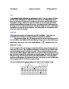
Whilst current is flowing in a circuit, free electrons in the conducting substances are vibrating electronic energy around the circuit. This energy is called potential energy or PE for short. The electrons are given PE in the power source, and it is then used to ‘power’ the components of the circuit by effectively ‘offloading’ a certain amount of energy at each individual item. The force of resistance is counteracting the flow of free electrons by acting as a buffer to these free-moving charge carriers, and therefore the more resistance there is, the less voltage and current there is in the circuit overall. If the wire is thinner then the electrons have less of a cross sectional area to bounce through, and the wire’s atoms slow down the free-electrons by impacting them. A similar scenario occurs if the wire is hot, as the wire’s atoms vibrate more and these reverberations also impact the free-electrons slowing them down. Resistance is clearly far less in the opposite situation to both of these scenarios. Other possible scenarios have been briefly mentioned in the ‘Affecting Factors’ section.
Repeated readings
In this experiment I have decided that during the final experiment, I shall take repeat readings. I have decided this as during the preliminary investigation, I have noticed that several readings are easily anomalous. If I should combat any erratic figures during the final experiment I can rely on a second set of readings, therefore making the experiment more of a fair test. It is to this effect that I believe repeated readings necessary and I shall take two sets of reading for each voltage experimented on.
Background information
During the course of the academic year, I have conducted an experiment to prove Ohm’s law of resistance, voltage and current. This law associates all three of the aforementioned units in a simple equation:
Voltage = Current x Resistance or V=IR
This proved that as voltage and current increased, so did the resistance of the wire. This is one of the many ideas that I base my hypothesis of the experiment on.
Prediction
I predict that in my final experiment, as the voltage increases, so will the current. I believe this as voltage is said to be the ‘pushing force’ or drive behind the current and so the higher the voltage is, the faster the flow of electrons in the wire. I also predict that higher than 8V the wire will burn. I believe this as whilst investigating my preliminary experiment, the wire burnt quickly on a voltage of 8V or thereabouts.
I predict that the shorter the wire becomes, the higher the voltage and current of that wire, I believe this because the shorter the wire becomes, the lower the resistance becomes as the free electrons in the circuit would have far less atoms in the Constantan wire to impact against subsequently lowering the resistance. I also believe that the higher the voltage and lower the current, the higher the resistance will be, I have concluded this from ohm’s law. Also I predict that the higher the voltage and current on a short length of wire, the higher the possibility of mass temperature rise and therefore open flame. This would ruin the experiment so as I have said before I shall only be using voltages less than and including 6v.
Final experiment
During this section of the investigation, using newly discovered knowledge from my preliminary experiment I shall aim to collect a set of accurate results to match my hypothesis.
Apparatus
During this experiment I shall need:
A digital ammeter
A digital voltmeter
A Constantan wire
A power pack
Sets of power leads
100cm ruler
Crocodile clips
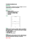
Diagram
Method
The apparatus was set up as shown in the diagram. The Constantan wire was mounted onto the ruler, and attached by both selotape and crocodile clips (one at 0 on the ruler, the other one was moved up and down the scale in order to change the overall length of wire included in the circuit) The readings were taken from both the ammeter and the voltmeter in two sets for each voltage. The readings were taken at a constant variation of 10 cm from 100cm to 20 cm (I haven’t taken any readings less than 20 as in the preliminary this tended to burn the wire) I took readings in three different voltages namely 2volts, 4volts and 6volts.
Results
2 volts, first set
Graph
2 volts, second set
Graph
4 volts, first set
Graph
4 volts, second set
Graph
6 volts, first set
Graph
6 volts, second set
Graph
Analysis
From the graphs above, it is clear that the resistance between varying voltages are very similar. As the voltage and current have increased the resistance has increased, as I have previously stated in my prediction, therefore Constantan wire obeys ohms law of resistance. The increase in resistance is due to more and more energy being put into the wire. That is to say as the voltage or the driving factor behind the free electrons flowing around the circuit increases, this increase in resistance is caused by the free electrons being passed around the circuit at much higher speeds and therefore deflecting off of more atoms that have more heat energy than those in shorter lengths of constantan wire. These atoms are hotter because more free electrons are passing through these lengths of wire, and deflecting off of more atoms, passing their kinetic energy to these atoms as heat energy. This is what causes the wire to heat up, and sometimes melt. During taking these results I have noticed that there are several linking factors. These are mainly current and voltage, as stated in ohms law.
Evaluation
I believe that my experiment in all is accurate for a GCSE standard coursework piece, although in research physics I believe that this experiment would be highly inaccurate. I do not believe that any of my readings are abnormal. From my work – mostly from the average set of results taken from all 6 sets, I can conclude that:
- Resistance in a wire is equal to the voltage divided by the current of the circuit
- With high voltages, the wire in the circuit heats up due to an increasing number of collisions of free electrons and atoms in the Constantan wire.
- As a wire decreases in length, the resistance increase
- As a wire increases in length, the resistance increases as does the voltage however the current decreases
- Constantan wire obeys ohms law
During the experiment I noticed several abnormalities however. If I had the power pack on for too long a period of time, the readings on both ammeter and voltmeter began to become more and more erratic. I believe this to be because the apparatus was not turned off, heat would have been building up in the Constantan wire so during the experiment I turned off the apparatus between readings. After I did this I noticed that this strange behaviour had stopped.
I also realised that using a rule and crocodile clips was clearly not the greatest means of measuring the length of wire as the lengths would clearly have not been at all accurate, and that the likelihood of using the exact amount of wire in the circuit was far outweighed by that of not doing so.
In the graph which I associated length of wire with resistance, it clearly showed a straight line through the origin (0,0). This line represents the phrase ‘proportional to’ therefore I also conclude that length of wire is proportional to the resistance of the wire.
Improvements
My work in this final experiment is far improved from that of my preliminary although it could easily still be improved further. I would improve it further by using more accurate means of measuring the voltage and current of the circuit, I would use various types of wire, I would vary the temperature of the wire and I would vary the cross sectional area of the wire. In this experiment, although I only varied the length of the wire, unwittingly I also have changed the temperature of the wire, as it increases as any current is passed through it, and as the shorter the subject wire becomes the hotter it also becomes. I would strive to collect resistance readings that were the same throughout the experiment as mine varied slightly.
Reliability
I believe that my results are viable for a GCSE standard piece of coursework although a research physician would discard them. I believe that collecting answers to two decimal places is also accurate enough for this experiment and that the slight variations of resistance between repeats is so small that the results could be deemed ‘accurate’.
Constant factors
In this investigation I have strived to make sure that the following factors remained constant:
- Cross sectional area
- Temperature of wire
- Type of wire
In this investigation, the cross sectional area or CSA would be maintained throughout readings, as the wire was not swapped during the experiments. This reason also dictates that the type of wire is also a factor that was kept constant. As I have mentioned before the temperature of the wire would have varied throughout the experiment, and as I have mentioned in the preliminary section of this investigation that with voltages higher than 8v the wire began to burn. This deviation in the temperature may have been the deciding factor as to why my readings for resistance were only slightly different.