The resistance of wire
Planning section
In the experiment I will be investigating the resistance of different wires and how at different lengths the voltage increases and decreases.
Variables and fair test
I intend to keep all the variables the same except for the one that I am testing which is the length to see how it affects the resistance and I intend to measure this accurately
Scientific knowledge
Copper
In a conductor, electric current can flow freely, in an insulator it cannot. Metals such as copper typify conductors, while most non-metallic solids are said to be good insulators, having extremely high resistance to the flow of charge through them. "Conductor" implies that the outer electrons of the atoms are loosely bound and free to move through the material. Most atoms hold on to their electrons tightly and are insulators. In copper, the valence electrons are essentially free and strongly repel each other. Any external influence which moves one of them will cause a repulsion of other electrons which propagates, "domino fashion" through the conductor.
Simply stated, most metals are good electrical conductors, most non-metals are not. Metals are also generally good heat conductors while non-metals are not.
Copper
How copper conducts electricity
Copper is a metal. It is made up of Copper atoms closely packed together.
If we could look closely enough, we would see that there are electrons moving about between the copper atoms. Each copper atom has lost one electron and become a positive ion. So copper is a lattice of positive copper ions with free electrons moving between them. (The electrons are a bit like the particles of a gas that is free to move within the edges of the wire).
The electrons can move freely through the metal. For this reason, they are known as free electrons. They are also known as conduction electrons, because they help copper to be a good of heat and electricity.
The copper are vibrating. Notice that they vibrate around the same place whereas the electrons can move through the lattice. This is very important when we connect the wire to a battery.
Conducting electricity through copper
We can connect a copper wire to a battery and a switch. Normally, the free electrons move about randomly in the metal.
When we close the switch, an electric current flows. Now the free electrons flow through the wire (in picture 3, they are moving from left to right - although they still move randomly as well).
have a negative charge. They are attracted to the positive end of the battery. The free electrons move through the copper, flowing from the negative to positive terminal of the battery (note that they flow in the opposite direction to ; this is because they have a negative charge).
The copper in the wire vibrate. Sometimes an ion blocks the path of a moving electron. The electron collides with the ion and bounces off it. This slows down the electron. Some of its energy has been transferred to the ion, which vibrates faster.
Magnanin
Manganin is an alloy which mainly consists of magnesium and it has a quite a low resistance.
On its own magnesium has a low resistance. Its resistance is shown below.
Constantan and Nichrome
Constantan tan is also an alloy and Nichrome is as well.
Nichrome mainly consists of nickel and nickel has quite a low resistance and its conductivity is shown below.
The structure of an atom
Matter has mass and takes up space. Atoms are basic building blocks of matter, and cannot be chemically subdivided by ordinary means.
The word atom is derived from the Greek word atom which means indivisible. The Greeks concluded that matter could be broken down into particles to small to be seen. These particles were called atoms
Atoms are composed of three types of particles: protons, neutrons, and electron. Protons and neutrons are responsible for most of the atomic mass e.g. in a 150 person 149 lbs, 15 oz are protons and neutrons while only 1 oz. is electrons. The mass of an electron is very small (9.108 X 10⁻²⁸ grams).
Both the protons and neutrons reside in the nucleus. Protons have a positive (+) charge, neutrons have no charge --they are neutral. Electrons reside in orbital around the nucleus. They have a negative charge (-).
It is the number of protons that determines the atomic number, e.g., H = 1. The number of protons in an element is constant (e.g., H=1, Ur=92) but neutron number may vary, so mass number (protons + neutrons) may vary.
The same element may contain varying numbers of neutrons; these forms of an element are called isotopes. The chemical properties of isotopes are the same, although the physical properties of some isotopes may be different. Some isotopes are radioactive-meaning they "radiate" energy as they decay to a more stable form, perhaps another element half-life: time required for half of the atoms of an element to decay into stable form. Another example is oxygen; with atomic number of 8 can have 8, 9, or 10 neutrons.

How are electrons organized around the nucleus?
All atoms would like to attain electron configurations like noble gases. That is, have completed outer shells. Atoms can form stable electron configurations like noble gases by:
- losing electrons
- sharing electrons
- Gaining electrons.
For a stable configuration each atom must fill its outer energy level:
1st: 2 electrons 2nd: 8 electrons 3rd: 8 electrons 4th: 8 electrons
Atoms that have 1, 2 or 3 electrons in their outer levels will tend to lose them in interactions with atoms that have ...
This is a preview of the whole essay
How are electrons organized around the nucleus?
All atoms would like to attain electron configurations like noble gases. That is, have completed outer shells. Atoms can form stable electron configurations like noble gases by:
- losing electrons
- sharing electrons
- Gaining electrons.
For a stable configuration each atom must fill its outer energy level:
1st: 2 electrons 2nd: 8 electrons 3rd: 8 electrons 4th: 8 electrons
Atoms that have 1, 2 or 3 electrons in their outer levels will tend to lose them in interactions with atoms that have 5, 6 or 7 electrons in their outer levels. Atoms that have 5, 6 or 7 electrons in their outer levels will tend to gain electrons from atoms with 1, 2 or 3 electrons in their outer levels. Atoms that have 4 electrons in the outer most energy level will tend to neither neither totally lose nor totally gain electrons during interactions.
Visualizing Atomic Orbit
The atomic orbital of the hydrogen atom can be visualized as a cloud around the nucleus. The orbital represents a probability of finding the electron at a particular location. Darker regions signify a greater probability. Shown below are the 1s (lowest orbital and the 2s orbital.
1s2s
Atomic orbitals do not always have the shape of a sphere. Higher orbitals have very unusual shapes.
2px3px
Metals conduct electricity because the atoms in them do not hold on to their electrons very well, and so creating free electrons, carrying a negative charge to jump along the line of atoms in a wire. Resistance is caused when these electrons flowing towards the positive terminal have to 'jumps' atoms. So if we double the length of a wire, the number of atoms in the wire doubles, so the number of jumps doubles, so twice the amount of energy is required: There are twice as many jumps if the wire is twice as long.
The thinner the wire is the less channels of electrons in the wire for current to flow, so the energy is not spread out as much, so the resistance will be higher: We see that if the area of the wire doubles, so does the number of possible routes for the current to flow down, therefore the energy is twice as spread out, so resistance might halve.
Intended method
In this investigation a simple circuit will be set up to read the voltage and current when the length of the wire changes. The length will range from 20cm - 100cm (1m) with intervals of 20cm. The length of the wire will be changed by moving the crocodile clip across the wire on a ruler. We decided that the best thickness of wire to use would be 24swg. This is because a thicker wire would cause too much heat, and the resistance of a thinner wire would be high and difficult to measure. The reason for this is that a thicker wire has less resistance, because there is more room for the electrons to travel through it.
We did preliminary tests to ensure that the wire did not get too hot, and how many cells to use in the circuit. The amount of energy supplied was important, as it would determine how hot the wire got. If the wire got too hot, energy would be given off as heat, and the resistance would be increased. We did a test that used the same piece of wire at different lengths with two different settings on the power pack (2 and 6). The results showed that with at 6, the resistance was higher due to the wire being hotter. For this reason I will use a setting of 2 to keep it a fair test.
The circuit should be set up as in the circuit diagram. It is important that the voltmeter is set up in parallel and the ammeter in series. The readings from the ammeter and voltmeter will be used to work out the resistance. This can be done using the formula: V=I/R
Plan (Method)
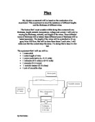
1) Collect all apparatus –I will need four metal wires - copper, Manganin, constantan and nichrome. I can obtain more results with four different types of wire which will then help me to get a better set of results by comparing and contrasting the results. I will also need a Metre ruler stick – I will be using a 1meter (100cm) ruler to measure each length of each metal wire as the marks are further apart on this ruler than on a smaller ruler e.g. 30cm ruler which will then lead to a higher degree of accuracy as it is being read clearer.
I will also be using digital and analogue volt meters which will be used to show the voltage of each wire at each length, I am using two voltmeters to calculate an average from the results which leads to a more accurate result.
I will also be using digital and analogue ammeters which will help me to ensure that the current is the same throughout the experiment and I am using 2 to calculate an average from the two readings to give an accurate reading
I will also be needing a set of wires which are 5 plug-to-plug cables and 4 plug to-croc-cables which are required to connect the circuit for example the analogue voltmeter to power pack. I will also need to be using a variable resister as this will control the current through the circuit we slide the top part to adjust the current. I will also need to use wire cutters as I will need to cut the wire to each length after measuring it very carefully. Finally I will need a power pack to provide electricity (current) to pass through it so the voltage and current can be recorded to calculate the resistance.
2) Next I will need to set the circuit up and I will be doing it as shown below:-
The ammeters, variable resistor, and the wire will be placed in series. The voltmeters will be placed in parallel to the wire and power pack as I need to find out the voltage through the piece wire not the whole circuit.
3) I will then need to take and record the readings from the two ammeters and voltmeters and I will need to keep the keep the amps to 0.3 to get the required reading to work out an average and compare it with my other results to ensure that the result isn’t anomalous. Using the variable resister I will keep the current 0.3.
4) I will them do the same test with the copper wire at different lengths (20, 30, 40, 50, 60, 80 and 100) by doing this I can acquire a series of results 2 contrast and compare which will den result in a more accurate end result.
5) I will then need to repeat this for each length of copper twice so that I have more than 1 result for each length so I am able to ensure that none of them are anomalous which I will need that to calculate the averages to reinforce my first result.
6) I will then repeat the above two steps for the three other metals (Manganin, nichrome and constantan) so I have three results for each length of metal wire so I can then plot these on a graph which will be another way of analysing my results.
Range of observations
For my experiment I shall be doing 7 different lengths of wire with three checks each and I will be doing two in-between experiments with three checks each and that shall be for each of the four types of wire. I am doing this so I am able to analyse my data better because it allows me to make sure that none of my results are anomalous.
Detailed scientific knowledge
Factors that affect the resistance of a wire
One factor will be the material used as it will contain atoms with a large number of electrons on its outer shell meaning that more electrons are available so in theory if it has a large amount of electrons on the outer shell it would have a lower resistance to that of a material with lower electrons in the outer shell an as each material has a different atomic structure the resistance will vary.
Atomic structure of copper:-
Electrons per energy level: 2, 8, 18, 1
Shell model
If the atoms in the wire are closely packed, then this will cause an increase in resistance, due to frequent collisions.
The length of the wire is also a factors the longer the wire the longer the collisions to get to the end of the wire causing more collisions between the electrons. So in theory the length should be directly proportional to resistance. So this will help me to show that as the length increases the resistance will increase so it will help me to predict some of the results.
Structure of Atoms
The number of protons, neutrons, and electrons in an atom can be determined from a set of simple rules.
- The number of protons in the nucleus of the atom is equal to the atomic number (Z).
- The number of electrons in a neutral atom is equal to the number of protons.
- The mass number of the atom (M) is equal to the sum of the number of protons and neutrons in the nucleus.
- The number of neutrons is equal to the difference between the mass number of the atom (M) and the atomic number (Z).
Knowing the structure of the atom will help me plan my experiment as I will need to be able to work out how many electrons in the outer shell and how its sets up so I will know the theory behind How an atom I set out so I will know the electrons collide and how and why it affects the resistance.
Resistance
‘Resistivity is a measure of the material's ability to oppose the flow of electric current’
The electrical resistance of a wire would be expected to be greater for a longer wire, less for a wire of larger cross sectional area, and would be expected to depend upon the material out of which the wire is made. Experimentally, the dependence upon these properties is a straightforward one for a wide range of conditions, and the resistance of a wire can be expressed as
The following table shows the resistance and the temperature coefficient at 20oc of the four wires that I am investigating.
Resistance occurs in a wire when the electrons which are traveling along the wire collide with the atoms of a wire and these collisions slow down the flow of the electrons causing resistance. So resistance then is the way of measuring how hard it is to move the electrons through the wire.
Resistance tries to slow down the current flowing through the wire so the larger the current the harder it is for it to flow the wire.
As we already know only certain materials can conducts electricity because of the way the particles are arranged in that material as in those materials free electrons are given energy and they then collide with neighboring free electrons and this affect is carried on thorough out the wire which then means that electricity is conducted and resistance is energy lost as heat as it involve collisions between free electrons.
Longer wires have more resistance than shorter wires, because in a longer wire there are more metal ions for the current to pass through. Thinner wires have more resistance than thick wires because in thicker wires there is more space for the current to pass through. If the wire is hotter, the metal ions will vibrate more and there will be more collisions between the metal ions and electrons, so there will be more resistance.
There are many factors which can affect the resistance including the material used as a copper wire is a better conductor than nichrome so nichrome will have a higher resistance.
Ohm’s law
Ohms law is what we use to work out the resistance it is the formula V=I*R (where V = Voltage, I = Current, R = Resistance). He discovered the relationship that the amount of steady current through a large number of materials is directly proportional to the potential difference, or voltage, across the materials. Thus, if the voltage V (in units of volts) between two ends of a wire made from one of these materials is tripled, the current I (amperes) also triple; and the quotient V/I remain constant.
With modifications, Ohm's law also applies to alternating-current circuits, in which the relation between the voltage and the current is more complicated than for direct currents. Precisely because the current is varying, besides resistance, other forms of opposition to the current arise, called reactance. The combination of resistance and reactance is called impedance, Z. When the impedance, equivalent to the ratio of voltage to current, in an alternating current circuit is constant, a common occurrence, and Ohm's law is applicable. For example, V/I = Z.
Knowing ohms law will help me to plan my experiment as I will be able to work out the voltage and the resistance and look at information from other web sites about how the voltage affects the resistance and how to work out the resistance from this formula so I am able to justify any predictions made.
Current
A current is a flow of charged particles through a circuit of conducting materials. Resistance tries to slow down the current flowing through. The larger the resistance of the current, the harder it is for the current to flow through it. Only certain materials conduct electricity because of the way the particles are arranged in the material
A current is made up of electrons. Conductors have the electrons mobile and free to move. This allows the current to take place of the electrons in the conductor and can easily pass through. Most metals along with some other materials are conductors.
An atom consists of a nucleus and orbiting electrons. These electrons can create a flow of current, so the more free electrons there are, the more conducting capability that material has; thus copper is more conductive that iron. Alloys tend to have less free electrons so they will be less conductive. The order of resistance is consequentially copper, Manganin, constantan then Nichrome increasingly.
Precision used with chosen apparatus
Analogue and digital voltmeter and ammeter - in the experiment I used both digital and analogue voltmeters as analogue voltmeters and ammeters are very likely to have parallax errors because of the needle and if the needle is bent or faulty it’ll give a false reading so when used with the digital ammeter and voltmeter I can see if that is happening, but using the analogue voltmeter and ammeter is good because it can detect the smallest of amps.
Variable resister – I am going to use a variable resister because in the school laboratory it is one of the most precise ways of alternating the current, it changes the current to avoid the heating affect which occurs if the current is to high (as the higher the current the high the resistance and it is given off as heat energy) so I am going to keep the current at 0.3 amps.
Crocodile clips – I am using these to connect the apparatus I have chosen to use these as they have a very small diameter (4/5mm) and are very easy to use.
Power pack – I have chosen to use this apparatus because it meant that I could keep the voltage at a constant amount which meant that my results would be precise and accurate.
1 meter stick – I am using a 1m stick to measure the length of the wire because the marks are further apart on this than a ruler so it can be read with a higher degree of accuracy and I was to use a smaller ruler e.g. 30 cm I would be more likely to make mistakes while measuring it.
5 plug-to-plug cables and 4 plug to-croc-cables – These are needed to connect the circuit together
Wire cutters – I need to use these to cut through the metal wires and I can make sure that I use these accurately by making sure that the wire is vertical before it is cut so it isn’t cut diagonally and a few mm’s longer or shorter than the desired length.
Power pack – This provides the electricity or the current to pass through the circuit. This will allow the voltage and the current to be recorded to find out and calculate the resistance. We used a power pack instead of batteries because power packs will supply continuous electricity and we can change the voltage. Batteries run out of electricity and only supply a certain amount of electricity.
Justified prediction
I predict that the longer the wire the higher the resistance because the resistance is directionally proportional to the length because an atom consists of a nucleus and orbiting electrons. These electrons can create a flow of current, so the more free electrons there are, the more conducting capability that material has; thus copper is more conductive that iron. Alloys tend to have less free electrons so they will be less conductive. The order of resistance is consequentially copper, Manganin, constantan then Nichrome increasingly so the longer the wire the higher the resistance because resistance occurs in a wire when the electrons which are traveling along the wire collide with the atoms of a wire and these collisions slow down the flow of the electrons causing resistance.
I also predict that as the length doubles so will the resistance because it is directionally proportional because when the length increases the number of atoms will increase meaning that there will be more collisions with the atoms causing a greater resistance so if you double the length you double the so if you double the length you double the number of atoms which then doubles the resistance. The longer the piece of wire, the further the distance the electricity has to travel. E.g. if I do an experiment using a 20cm wire and the resistance is 1.5 ohms, if I double the length up to 40cm, the resistance should be 3 ohms.
I predict that each wire will have a different resistance with some with a very low resistance and some with a very large resistance especially since some are better conductors of energy I predict that the constantan wire will have more resistance than copper because it is not a very good conductor, whereas, copper is an excellent conductor so it will have a low resistance because electricity can pass through it pretty easily without any obstacles. I predict that nichrome will have the highest resistance because it is an alloy made up of nickel and chromium. I think that Manganin wont have a high resistance because it has 84% copper in it.
I think that constantan will have the 2nd highest resistance because Constantan is a semi-conductor because it has some copper, nickel and added impurities in it. Referring to my scientific knowledge, semi-conductors have a higher resistance than conductors.
I think that copper will have the lowest resistance because it is a pure metal and it is an excellent conductor so the current will flow through it freely. It will have some resistance, but not much. It depends on the electrons and the atomic structure.
I predict that at 100cm (highest value) the nichrome wire will have a resistance of approximately 4.6 ohms. For the copper wire, I predict that at 100cm the resistance will be approximately 0.6 ohms. For the Manganin wire, I predict that at 100cm, the resistance will be approximately 2 ohms. For the constantan wire, I predict that at 100cm, the resistance will be approximately 4.5 ohms.
I predict that at 100 m the copper wire should have a resistance of 0.6 ohms and at the same length the nichrome wire would have a resistance of 4.6 ohms and my Manganin wire will have a resistance of 2 ohms and constantan will be at 4.5 ohms.
I from this I can predict the placement of the result on my graphs with the metal with the highest resistance first nichrome then Manganin then constantan then copper, copper was he obvious lowest result as it used for most wire so it must have a very low resistance.
On the next page there are the predicted graphs of all four metals.
Secondary source data
For my secondary source data I shall be using other pupil’s results from my class and I will compare those to mine. I am going to be comparing there data with mine on graphs to see who’s are the most accurate, match my prediction the most, and if most importantly they are along the amounts. I will also be using the focus education software to reinforce my prediction that as the length rises so does the resistance.
Results
Precision
I used my equipment precisely by
- Ammeters- I made sure that the needle was at exactly 0.3 amps when and that this reading was the same on the digital ammeter.
- Voltmeter- when I was recording the results from the voltmeters I made sure that I read it properly and didn’t make a parallax error and I did this by making sure that I read it at eye level and I double checked the readings on the digital voltmeters.
- Ruler- when measuring my wire I first made sure that the wire was perfectly strait then I held it exactly at the first mark while someone else cut it with the wire cutters; we also cut the wire when it was vertical so make sure that we cut it in a way that one edge was longer than the other.
- Power pack- after each experiment I switched the power pack off to make sure that the wire didn’t get too hot because if the wire remains hot there will still be collisions atoms and this will affect the results and using a power pack is better than using cells because if gives a continuous amount of energy whereas a battery loses it power.
- Using secondary results from other pupils to check if my results are accurate.
- Testing each piece of equipment to ensure that they are working properly.
Results tables
My results tables are on the next page my secondary source data from another group follows then other secondary source data.
Analysing evidence
Numerical method
I didn’t only us averages to produce my data in this investigation I used formulas one of which being the formula for resistance which is:-
R=V/I
An example of me using this formula is below:-
Voltage (V) =0.4
Amps (I) =0.3
R=V/I
R=0.4/0.3
R=1.33
Conclusions drawn from processed evidence
The results given from the line graphs clearly indicate how the length of the wire compares to the resistance, although there were a few anomalous results but I corrected them before plotting them on my graph and I have one on to explain these in my evaluation.
In my justified prediction I stated that the resistance will be proportional to the length of the wire and my graphs roughly show this is correct as it shows a positive correlation between the length and resistance which means that as the length increases so does the resistance.
The theory behind this is that in a wire as it increases it will have many more atoms in its way causing an increase in the resistance. As electricity is the movement of electrons moving through the wire any interference which will then result as energy being given off as an unwanted material e.g. heat will cause the atoms to slow down. This means that if there are a large number of atoms there is a higher chance of them colliding so the resistance is increased and m graph proves this
I drew a graph of my secondary source of results (another group‘s results), their results were different from mine but only slightly and overall their graph shows that they had less anomalous results than us which proves that their results were the most accurate and they also followed the same trend as min which proved that my data wasn’t incorrect and again prove my prediction that as the length of the wire increases so does the resistance.
Then, I drew a graph of the focus educational software results. Again our results were pretty similar and it proved my prediction.
Explaining the conclusion using theory
When I refer back to my scientific knowledge in theory when you double the nuclei the positivity of the atoms should attract the free atoms but in practice no matter how much you repeat this experiment it doesn’t occur in proportion. This is due to the heating affect in the atmosphere which results in an increase of collisions tainting my results and it is hard to control this affect and w dint have the proper equipment in the school laboratory to control so it will always have an effect on my results. The heating affect is where when heat passes through the atoms in the wire these atoms vibrate and as they vibrate create a higher chance o colliding with atoms which then causes an increase in resistance. The main problem with my experiment was that I couldn’t control every variable and because of this my results weren’t directionally proportional so my results weren’t totally accurate.
Prediction supported by results
There were slight differences in my predicted results than in my results as I had to take into account the heating affect. I had earlie predicted that
I predicted that at 100cm, the copper wire would have a resistance of 0.6 ohms, when my actual result showed that it was 0.4 ohms which wasn’t too far off. I also predicted that 100cm, the nichrome wire would have a resistance of 4.6 ohms and my actual result was 4.6 ohms. For the Manganin wire, I predicted that the resistance at 100cm would be 2 ohms. My actual result was 2.1 ohms. For the constantan wire, I predicted that at 100cm, the resistance would be 4.5 ohms. My actual result was 4.6 ohms. There had to be slight differences due to the heating affect which I had mentioned earlier. I also predicted the order of my graphs and they had come out exactly as predicted with nichrome then Manganin then constantan then copper.
My predicted results were very close to my actual results.
I drew a graph of my secondary source of results (different group‘s results), their results differ from mine but overall their graph shows that they had less anomalous results than us which proves that their results were the most accurate.
Then, I drew a graph of the focus educational software results. The copper wire is less steep than mine. The Manganin and constantan wires are much closer together than mine but the nichrome wire is practically the same.
My predicted graph, secondary source and tertiary source of data graphs all have similar shapes/slopes. This also proves my prediction to be correct.
Conclusions drawn from processed evidence
Nichrome
For Nichrome wire, the resistance at 20cm[A] was 0.98 ohms. The resistance at 40cm[B] (double 20) is 1.83. According to ohm’s law, the length of wire is proportional to the resistance, so if you multiply 0.98 by 2, it is 1.96. I got 1.83 which is close but not exactly the correct answer. At 80cm[C] (double 20) the resistance is 3.65. If you double 1.96, the answer is 3.92. My answer is slightly lower than it should be.
My graph does not match the theory 100%.
Constantan
For constantan wire, the resistance at 20cm[A] was 0.34 ohms. The resistance at 40cm[B] (double 20) is 0.72. According to ohm’s law, the length of wire is proportional to the resistance, so if you multiply 0.34 by 2, it is 0.68. I got 0.72 which is close but not exactly the correct answer. At 80cm[C] (double 20) the resistance is 1.44. If you double 0.68, the answer is 1.36. My answer is slightly higher than it should be.
My graph does not match the theory 100%.
For constantan wire, the resistance at 20cm[A] was 0.43 ohms. The resistance at 40cm[B] (double 20) is 0.767. According to ohm’s law, the length of wire is proportional to the resistance, so if you multiply 0.34 by 2, it is 0.68. I got 0.72 which is close but not exactly the correct answer. At 80cm[C] (double 20) the resistance is 1.44. If you double 0.68, the answer is 1.36. My answer is slightly higher than it should be.
My graph does not match the theory 100%.
Relating my evidence to that in my prediction and scientific knowledge
In my prediction I said that the resistance will be proportional to the length of the wire. My graph proves my prediction to be more or less correct. It shows a positive correlation which means that as the length increases, the resistance increases aswell.
The theory behind this is that in any metal wire, there are a number of atoms and free electrons. Electricity is the movement of these electrons through the wire. Resistance is caused when the free electrons moving through the wire collide with the atoms making their path through the wire more difficult. This means that if there are more atoms in the way to collide with free electrons, the resistance is increased. In a length of wire, there are atoms and free electrons, so the longer the wire, the more atoms. Therefore, there will be more collisions between the atoms and electrons, this will increase the resistance. My graphs prove this.
Evaluation section
Accuracy of observations
I feel that my results are reasonably accurate as I had fixed my any anomalous results during writing out the tables and my lines of best fit were quite accurate and my secondary source data was very accurate and my tertiary source of data matched my predicted data well because those predicted results were perfectly accurate. I know that my result were not perfectly accurate because of the heating affect and I have one a graph of standard deviation to sow how they differed and I know that this was down to the heating affect. I know that my results weren’t accurate and I know this as they don’t fit in the line of best fit and the resistance and length weren’t directionally proportional.
The results for the secondary source of data were not 100% accurate either as there were quite a few points that fell outside the line of best fit as they would have suffered the affects of the heating affect but My tertiary set of data (Focus Educational Software) was 100% accurate. There were no anomalous results, I think this is because the software was done really accurately as they had the right equipment to prevent the heating affect.
Anomalous results
In the Analysis and the graph I have shown two main anomalous points, this means that there must have been a slight error in my experiment. As the wire, length is bigger at these points I found it harder to stretch it out and consequently, measure it accurately. Although the graph is overall accurate and the results precise it is easy to see, the anomalous averages plotted because they do not all lie along the same best-fit line. The graph shows that my results are reliable as there are only two main anomalous points, (which are easily accounted for) to improve the reliability of my results, I could do more repeats in doing this my average would be more reliable.
As I increased the wire length, the wire became hotter and gave off heat. I think one of the reasons why my experiment is quite accurate is because I tried to measure the wire as accurately as possible. The metre rule was taped onto the workbench. The wire was stretched until it was nearly in a straight line so a bit was overlapping at each end. As the metre rule was curved and worn down at the corners it was slightly hard to see where 0cm was. Finally, the inside edge of the crocodile clips were placed at the appropriate point. I still however would like to make the measuring more accurate
Suitability of procedure
I think that I had completed this experiment quit well as the only main factor disrupting my results was the temperature not remaining constant but that couldn’t be helped as I couldn’t control this variable but I do think I could have improve it but it was cheap, reliable and repeatable. The improvements that I could have made were to keep the wire at a more accurate constant temperature so the shorter wires would not get so hot and give inaccurate readings. This could be done by covering the wire in a plastic coat so it would keep it cool, or you could use a condenser. Another option is to use longer wire lengths so the wires don’t get hot easily and quickly. To speed up the pace of the experiment, an ohmmeter could be used to directly calculate the resistance. Out experiment was too slow and took a lot of time. Instead of reading the voltage and calculating the resistance, an ohmmeter could be used. This would speed up the method and give more accurate readings.
Reliability of results
My end results were reliable because:
- I kept the current constant at 0.3 amps
- Cut the wire accurately by making sure it wasn’t cut at an angle
- Measure the wire correctly by using a meter stick
- Measured the resistance using a calculator and I had double checked my results
- Ammeters and voltmeters (analogue) were read at eye level and (digital) would give me a double check and a very precise reading of up to 2 decimal points.
- We used a variable resistor to keep the amps at 0.3
- The width of wire was always 24 SWG
And I couldn’t control the temperature but from the above you can see that my variables were controlled quite well.
Does my evidence support my conclusion?
My graph result doesn’t match the theory 100%. My secondary source of data graph doesn’t match the theory 100% either, so no my evidence doesn’t support a definite conclusion. Although my results were reasonably accurate but it isn’t that accurate that it would support a definite conclusion but this was due to out side factors (temperature). I feel that if this isn’t happen I would have gotten completely accurate results.
My tertiary set of data (Focus Educational Software) was 100% accurate. There were no anomalous results; I think this is because the software gave me data that had no other variable then the length so the temperature wasn’t an issue.
Expanding my investigation
As well as making these modifications, I could also expand on my investigation by testing the same wire but different widths of that wire. I would do this if I had more time to complete it. I think the circuit and method used was quite suitable although I would make the modifications above to improve my results. If I did this experiment again I would defiantly use top quality equipment, I would probably control the temperature and use pointers instead of crocodile clips. After changing those few things, there is not really much difference to how I would do the experiment again.
Improvements that could be made to the experiment
If I was to improve my experiment I would have to this by keep the wire at a more accurate constant temperature so the shorter wires would not get so hot and give inaccurate readings. This could be done by covering the wire in a plastic coat so it would keep it cool, or you could use a condenser. Another option is to use longer wire lengths so the wires don’t get hot easily and quickly.
To speed up the pace of the experiment, an ohmmeter could be used to directly calculate the resistance. Out experiment was too slow and took a lot of time. Instead of reading the voltage and calculating the resistance, an ohmmeter could be used. This would speed up the method and give more accurate readings.
Does the evidence support a definite conclusion?
My graphs and my secondary sources graphs do not match my fully match my theory. Although my results were reasonably accurate they aren’t accurate enough to support a reasonable conclusion.
I think that my results were mainly affected by the heating affect and if this didn’t occur there wouldn’t have had an anomalous results and it would support a definite conclusion.
My results were not 100% accurate; I know this because not all of my results fall on my line of best fit. If my results matched the theory 100%, all the points would be in a straight line and there would be no points outside of the line of best fit.
The results for the secondary source of data were not 100% accurate either as there were quite a few points that fell outside the line of best fit.
The reason why my results do not support a definite conclusion is because of not being able to control the temperature variable. This had a big affect on my results.