room affecting my results so I built a small tunnel out of
cardboard and put it over the end of the hair dryer so that the air
would travel straight down the tube towards the cup
anemometer. However I couldn’t get the wind to blow over all of
the cup anemometer, this was a problem as in out in natural
wind all of the sides of the cup anemometer would be affected
by the wind, whilst my cup anemometer was only blown on one
side. In my experiment there was no wind resistance by the
side that was not facing the hair dryer. This meant that the
anemometer was rotating faster than it would have in natural
wind.
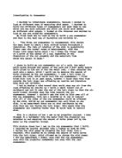
This is a picture of how I set up my propeller project. I then
plugged in a voltmeter into the motor that the propeller was
attached to and measured the amount of volts given off by the
motor as the propeller turned.
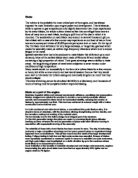
This picture shows how I set up the cup anemometer that I built.
I recorded my results straight into a laptop to save me time.
I varied the wind speed by plugging the hair dryer into a
rheostat. This enabled me to change the amount of volts going
into the hair dryer, which allowed me to change the wind speed.
I did the experiment 3 times, once with the cup anemometer,
once with the propeller anemometer and once with the real
anemometer.
Wind Speed in
m/s
Cup Anemometer
Volts Output
Propeller Anemometer
Volts Output
2.01
0.114
0.043
2.15
0.233
0.052
2.4
0.348
0.06
2.6
0.462
0.067
2.75
0.548
0.073
2.94
0.63
0.08
3.08
0.7
0.086
3.2
0.765
0.091
3.36
0.836
0.098
3.49
0.9
0.103
3.6
0.96
0.107
3.72
1.024
0.113
3.87
1.074
0.119
3.95
1.145
0.121
4.11
1.198
0.125
4.23
1.251
0.129
4.4
1.294
0.133
2.“There are several propeller anemometers which employ
lightweight molded plastic or polystyrene foam for the propeller
blades to achieve threshold speeds of 0.5 m/s. This type of
anemometer may be applied to collecting mean wind speeds
for input to models to determine dilution estimates and/or
transport estimates. Because of their relatively quick response
times, some having distance constants of about one meter,
these sensors are also suitable for use in determining the
standard deviation of the along-wind-speed fluctuations, u .
Care should be taken, however, in selecting a sensor that will
provide an optimal combination of such characteristics as
durability and sensitivity for the particular application.”
I also looked at my project on Picoscope on the computer,
which helped me understand what the propeller was doing as it
spun around. I produced this picture from the Picoscope.
This shows the amount of volts being produced in 1 second. I
blew the propeller just as I marked 1 second on the Picoscope.
From the results of the 3 different anemometers I managed to
produce this graph on excel. This shows both the cup and the
propeller anemometers.
From this graph you can see that the cup anemometer which
is in pink produced very little volts from the same amount of
wind as the propeller anemometer. You can see from this graph
that the cup anemometer has a much straighter line, this means
that it is more reliable as there is no deviation in its
straightness. However the propeller anemometer did produce
many more volts, but was less accurate as its line of results
was not straight. It also failed to work as lower wind speeds,
whilst the cup anemometer would have continued to work at low
wind speeds. The cup anemometer had a very linear line as all
the points lie on a straight line that I produced, whilst the
propeller anemometer is not very linear as only 2 points lie on
the straight line I produced using excel.
When I looked at the propeller anemometer I could see that as
the wind speed increased the motor increased its volts much
more efficiently.
This graph shows that as the wind speed increased the
propeller became much more efficient and started to produce
many more volts than it was at the beginning. This means that
this propeller anemometer that I made would be far more
effective at higher wind speeds.
" There are several mechanisms that can be used to convert the
rate of the cup or propeller rotations to an electrical signal
suitable for recording and/or processing. The four most
commonly used types of transducers are the DC generator, the
AC generator, the electrical-contact, and the interrupted light
beam. Many DC and AC generator types of transducers in
common use have limitations in terms of achieving low
thresholds and quick response times. Some DC generator
transducers are limited because the combined effect of brush
and bearing friction give a threshold speed above 0.5 m/s
(above 1.0 mph). However, some anemometers employ
miniaturized DC generators which allow thresholds below 0.5
m/s to be achieved. The AC generator transducers eliminate the
brush friction, but care must be exercised in the design of the
signal conditioning circuitry to avoid spurious oscillations in the
output signal that may be produced at low wind speeds.
Electrical-contact transducers are used to measure the “run-of-
the-wind”;i.e., the amount of air (measured as a distance)
passing a fixed point in a given time interval; wind speed is
calculated by dividing run-of-the-wind measurements by the
time interval"(3)
This extract explains how it is possible to measure a turning
object such a propeller. You can do it in a number of ways such
as using an LDR (light sensitive resistor) and measure the
amount of pulses it gives off. however for my project I looked at
using a voltmeter to measure the amount of volts given off,
because I found this the easiest way and the most accurate way
of getting results without them being too difficult to obtain.
I also investigated different ways of measuring wind speed
such as a weather vain that u could put into the wind and
measure the change in angle using either a LDR or a strain
gauge that could measure the amount of strain being put on the
vain by the wind. A wind sock can also be used to see the
intensity of the wind, however this is very inaccurate and it is
only possible to see if there is no wind or lots of wind. A wind
sock can also be used to tell the direction of the wind which is
an added advantage.