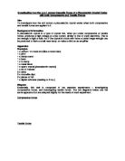
1 x set of masses
2 x wires
2 x crocodile clips
2 x pieces of foil
1 x digital voltmeter (reading to 2 d.p.)
Diagram
Essentially, this task is composed of two separate experiments – investigating compressive forces, and investigating tensile forces. The two diagrams below use the same apparatus but are adapted slightly for the needs of each experiment.
Compressive forces
Tensile forces
Notes:
- The G-Clamp is used to clamp the clamp stand to the table and prevent it from moving. This is essential and the clamp must be tightened to ensure accurate results. The boss must also be tightened around the wooden block.
- Superglue will be used to glue the quartz to the metal block and rod.
- The wires were connected to the quartz by super-gluing strips of aluminium foil to either end of the crystal and using crocodile clips to attach the wire to the foil.
- The distances between the centre of mass of the weights to the pivot, and the centre of the quartz crystal to the pivot are the same.
- The centre of mass of the rod is above the pivot.
Making the experiements fair/accurate
The experiment can be made accurate in the following ways:
-
Using a rod and block made of metal, not wood. This means that the wood is unlikely to dent and most of the force provided by the moment will be used to compress/stretch the crystal.
-
Using an accurate voltmeter (one that is digital and reads up to 2 s.f.).
-
Making sure the distances from the masses to the pivot and the crystal to the pivot are the same. This means that the force applied on the left is equal to the compressive/tensile force felt by the crystal so no complicated/unnecessary moment calculations have to be made
-
The centre of mass of the metal rod is above the pivot. This is so the mass of the rod does not have to be taken account when considering the compressive/tensile force felt by the crystal.
The experiment can be made fairer by doing the following:
- Making sure the same apparatus is used each time, especially the crystal.
- The 0N reading for both experiments on all repetitions should be the same – if it is not, check the apparatus set-up.
Method – compressive forces
The apparatus was set up as above but without any mass on the left side of the metal bar. The reading on the voltmeter was taken. A 100g mass was then placed on the left hand side of the bar and a voltmeter reading taken. Another 100g mass was stacked on top of the 1st mass and another voltmeter reading taken. This was repeated for masses from 0g to 1kg in 100g increments so 11 readings were taken all together. Repeat the experiment 3 times to produce triplicate results.
Method – tensile forces
The apparatus was set up as in the diagram but with no masses loaded on the end of the string. The reading on the voltmeter was taken. A 100g mass was then attached to the string and a voltmeter reading taken. Another 100g mass was then attached to the string and another voltmeter reading taken. This was repeated for masses from 0g to 1kg in 100g increments so 11 readings were taken all together. Repeat the experiment 3 times to produce triplicate results.
After these experiements, a graph of mass (grams (g), x-axis) and potential difference (volts (V), y-axis) can be plotted for each experiment. The lines can be drawn on the same graph to highlight any difference between the emf produced by compressive and tensile forces.