All these factors must be kept constant to make the investigation fair. The same apparatus must be used throughout the investigation. It is also important to take three repeats and find the mean so if one result is very inaccurate, the others will average it out.
Research
All materials, solid, liquid or gases are made up of atoms. The atoms themselves consist of a central bit, called the nucleus, made up of particles called protons (which have a + electrical charge) and neutrons (which have no charge) Orbiting around the nucleus are electrons which are very tiny and have a - electrical charge. One can think of the electrons orbiting in layers like the rings of an onion, and it's the ones in the very outside layer, the outer shell, that are the most important when thinking about conduction.
In metals, the outermost electrons are held only very weakly to the atom and often wander away from it and go to the nearby atom or one a bit further away. These wandering electrons are called conduction electrons and the more of these there are, for a given volume of metal, the better the metal will be as a conductor of electricity. When you connect a battery across a wire, one end becomes + and attracts the conduction electrons, which drift towards that end of the wire. But the electrons have obstacles to face because the metal atoms are jiggling about because of their thermal energy and so the electrons collide with them and are knocked all over. It's this difficulty that the electrons have in moving along the wire that we call resistance.
Resistance involves collisions of the current-carrying charged particles with fixed particles that make up the structure of the conductors. A resistor is a material that makes it hard for electrons to go through a circuit. Without resistance, the amount from even one volt would be infinite. Resistance occurs when electrons travelling along the wire collide with the atoms of the wire.
The unit of resistance is Ohms and the symbol is:
The higher the resistance, the lower the current. If there is high resistance, to get the same current a higher voltage will be needed to provide an extra push for the electricity.
Some metals have less resistance than others. Wires are always made out of copper because copper has a low resistance and therefore it is a good conductor. The length and width of a wire also has an effect. In this investigation I will investigate how the diameter of a wire will affect the resistance in the circuit.
Resistance opposes the flow of an electric current around a circuit so that energy is required to push the charged particles around the circuit. The circuit itself can resist the flow of particles if the wires are either very thin or very long.E.g. The filament an electric light bulb
Ohm's law
He discovered relationship that the amount of steady current through a large number of materials is directly proportional to the potential difference, or , across the materials. Thus, if the voltage V (in units of volts) between two ends of a wire made from one of these materials is tripled, the I (amperes) also triple; and the quotient V/I remain constant. The quotient V/I for a given piece of material is called its resistance, R, measured in units named ohms. The resistance of materials for which Ohm's law is valid does not change over enormous ranges of voltage and current. Ohm's law may be expressed mathematically as V/I = R. That the resistance, or the ratio of voltage to current, for all or part of an electric circuit at a fixed temperature is generally constant had been established by 1827 as a result of the investigations of the German physicist George Simon Ohm.
Alternate statements of Ohm's law are that the current I in a conductor equals the potential difference V across the conductor divided by the of the conductor, or simply I = V/R, and that the potential difference across a conductor equals the product of the current in the conductor and its resistance, V = IR. In a circuit in which the potential difference, or voltage, is constant, the current may be decreased by adding more resistance or increased by removing some resistance. Ohm's law may also be expressed in terms of the , or voltage, E, of the source of electric energy, such as a battery. For example, I = E/R.
With modifications, Ohm's law also applies to alternating-current circuits, in which the relation between the voltage and the current is more complicated than for direct currents. Precisely because the current is varying, besides resistance, other forms of opposition to the current arise, called reactance. The combination of resistance and reactance is called , Z. When the impedance, equivalent to the ratio of voltage to current, in an alternating current circuit is constant, a common occurrence, and Ohm's law is applicable. For example, V/I = Z.
With further modifications Ohm's law has been extended to the constant ratio of the magneto motive force to the magnetic flux in a .
Resistance values in electronic circuits vary from a few ohms, W, to values in kilohms, kW, (thousands of ohms) and Meg ohms, MW, (millions of ohms). Electronic components designed to have particular resistance values are called resistors.
Prediction
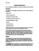
My hypothesis is that the thinner the wire, the higher the resistance. The thicker the wire, the lower the resistance.
This is because the thinner the wire is, the fewer paths there are for electrons in the wire therefore the harder it is for current to flow. This results in the energy not being able to spread out as much, so the resistance will be higher. This theory is similar to that of a door, where people represent the electrons and the door represents the diameter of the wire. If the door is wider, more people can get through, more easily. If the door is small, people have more difficulty and not as many people can walk in or out of the door. It is the same principal for electrons. If the diameter of a wire is thicker more electrons can go through the wire, therefore less resistance. The atoms from the metals cannot stop or collide with as many electrons because the diameter of the wire is larger. This can be seen in the diagram on the next page.
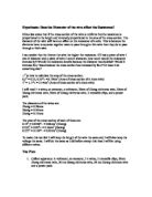
From my preliminary work, I can see that if the area of the wire doubles, so does the number of possible routes for the current to flow down, therefore the flow of electrons are twice as spread out, so resistance might halve,
I.e. Resistance 1/Area.
This can be explained using the formula
R = V/I
Where R=Resistance, I= Current, V=Voltage
When there is twice the current, and the voltage is the same, R (resistance) will halve. I did some research and in a book called 'Ordinary Level Physics' By A. F. Abbott, it says 'that doubling the area will therefore halve the resistance'- in other words the resistance of a wire is inversely proportional to its area, or R 1/A, but we are measuring diameter so the following calculations have to be made:
.
Safety
Whilst doing the investigation, it is important to keep safety into consideration. The scissors should only be used for cutting the wire to the appropriate length and for no other reason. Before using the power pack, the pointer should point at 0 volts. It is important to be careful while using the power supply. While handling live wires, it is essential to be careful. The voltage should be kept low because of the safety factor and the wires heating up.
Reliability
To make the experiment reliable, all apparatus must be checked to see if it is functioning properly and is giving a true reading. This will partly avoid systematic error. Another way to make the experiment reliable is to use two methods: to do the investigation in two different ways to measure the resistance when the diameters are changed. If one method contains systematic error or is very inaccurate, the other method will be used to recognise that.
Precision
I will take as many different results as possible so that there a wide range of results and that I am able to arrive at a good conclusion. To increase the accuracy of the experiment I will do repeats for all the experiments so when the mean is taken, an accurate table is drawn up and if one result is anonymous the other two results would contrast the anonymous result.
Preliminary work
Whilst doing preliminary work I will investigate the following:
· Get some sort of idea whether there is a connection between the diameter of the wire and the resistance within the circuit.
· Find out what kind of figures the resistance are for different diameters.
· Write the results of the preliminary work in a table below.
· Find out what length of wire should be used throughout the experiment.
· Find the appropriate apparatus and use them.
· Investigate ways of making the experiment fairer and more reliable.
· Think about two methods of doing the investigation to make it more reliable and refine methods of doing the investigation.
· Think about what materials (two: to make sure my conclusion works for all materials) should be used.
· Investigate the range of results, which will be appropriate and can be plotted in a graph to show some sort of connection.
· Think about what diameters or gauges should be used and state why they are being used.
· The verification of techniques is important whilst doing preliminary work and to decide adjustments, which will have to be made whilst having precision and reliability in mind.
· Think about the appropriate length of the wire whilst doing the investigation. This can be found whilst doing preliminary work. The appropriate length will be one, which is easy to work with and has more precision.
.
Preliminary Method
The aim of preliminary work is to find apparatus, make adjustments and investigate other factors listed above. With this in mind it is important to collect sufficient data but it is important not too contain too much data. The preliminary work is not designed for collecting data but for investigating the factors above. It is for this reason that the extremes will be taken. This means the highest and lowest diameter that can be obtained will be used as well as one or two in the middle. The three materials, which are available in more than three diameters, will be tested and in the conclusion, the best two materials will be stated. It is also important to find the appropriate length so a 50cm and 100cm length of wire will be tested and again in the conclusion, the most appropriate length of wire will be stated.
The apparatus will be set up as shown in the diagram. A piece of wire will be cut of 50 cm and 100cm (They will both be tested). The 50cm wire will be placed in the middle of the circuit. It will be placed on the ruler and stuck down with masking tape. Crocodile clips will be placed on either side of the wire and the resistance will be measured using an ohmmeter.
Three materials will be tested and two materials will be picked out of Constantan, copper and nichrome. The investigation will be carried out of carry out by measuring the resistance of different materials and two different lengths of wire. This will be done using an ohmmeter and the resistances of different diameters of different materials will be measured in ohms. The range of results will be investigated and decide whilst doing the preliminary work. The resistance of different diameters of wire will be measured whilst keeping other variables such as length and material constant. The results will be written down in a results table on the next page. I will find resistances of three different materials in order to decide which material will be used. In the real experiment the second method will also be used by which the resistance can be calculated by finding the potential difference and the current and using the formulae below to calculate the resistance as a test if the method is easy and it works. In the preliminary work, it is best to leave this alone because preliminary work is not designed to collect data.
Resistance= voltage
Current
Preliminary results
All the beneath results were taken whilst a 50cm wire was used.
The following results were taken from Nichrome:
The following results were taken from copper:
The following results were taken from constantan.
The following results were taken when a 100cm piece of wire was used:
The following results were taken from Nichrome:
The following results were taken from copper wire:
The following results were taken when constantan wire was used:
Preliminary conclusion
There is clear evidence from the preliminary results that:
1) Copper will not be used because the results are very random and because copper has a low resistance. This means copper is liable to be inaccurate and very imprecise. The smaller the resistance the larger the percentage error which can occur and since copper has a very low resistance, it will have a very large percentage error making the results inaccurate. The other two materials show a greater consistency and show there are patterns and trends. They also have high resistances, which not only are easier to work with but also have a small percentage error and it is easy to observe changes. This is because the other metals have a high resistance. Other metals could not be used because it is not widely available.
2) The length, which is better to use, is the 50cm wire because although the 100cm has higher resistances and therefore less percentage error, the 50cm wire is easier to handle, measure and cut. In other ways the 50cm wire is more accurate, for example during the preliminary experiment the wire, especially the thicker and longer wires could not placed straight on the ruler and so the length could not be measured properly. The longer the wires, the more bent the wires were and the more inaccurate the results would be. This is the reason for using pieces of metal wire, which are 50cm long, in the method.
3) The range, which should be used in the real experiment, is from 24 gauges to 38 gauges in 2 gauge intervals. This means that 24, 26, 28, 30, 32, 34, 36 and 38 gauge will be used. This range of 8 values is going to be used because the range is sufficient to plot a graph, find trends and patterns and those gauges are easy to obtain. It will also be used because those values have high resistances, which means there will be less percentage error and the results will be more accurate. It is important to take as many different measurements as possible so that there can be a good spread of results so that I am able to arrive at a good conclusion.
During the real experiment only the 50cm wire will be used, constantan and Nichrome will be used and data will be collected from the gauges between 24 and 38 inclusive in 2 gauge intervals. This should enable me to get enough data and to test if different lengths and materials work for my conclusion. The method will be accurate as repeats will be taken and the following materials and lengths have been chosen in preliminary work. The method will be reliable because two techniques will be used.
Apparatus
The following apparatus will be used for the first method (ohmmeter):
An ohmmeter, two leads, Constantan wire-24 ,26 ,28 ,30 ,32 ,34, 36, 38 gauge, nichrome wire- 24, 26, 28, 30, 32, 34, 36, 38 gauge, scissors, meter rule, crocodile clips, Masking tape
The following apparatus will be used for the second method (voltage/current):
A Voltmeter, Ammeter, crocodile clips, six leads, Constantan wire- 24, 26, 28, 30, 32, 34, 36, 38 gauge, nichrome wire- 24, 26, 28, 30, 32, 34, 36, 38 gauge, Scissors, meter rule, power pack, rheostat, masking tape.
Method 1
The apparatus was set up as shown in the diagram. A 50cm piece of Nichrome wire was cut, of gauge 24 using a scissors and was placed on a ruler. Masking tape was used to stick the wire down. Crocodile clips were connected to the wire at each end and the resistance was measured and noted down using an Ohmmeter to measure the resistance. The wire was then taken out and another 50cm nichrome wire was cut but this time gauge 26 was used and its resistance was measured. This method was also used for gauge 28, 30, 32, 34, 36, 38. Once the results were taken, Instead of using Nichrome wire, constantan wire were used so when analysing the data, I can be surer that my theory works for all metals, however I still cannot be certain because I have not tested all metals. With constantan, the resistance was measured again for gauges 24, 26, 28, 30, 32, 34, 36, 38. For each reading, three repeats were taken so a mean could be taken and there would be more precision. The resistance for the leads was measured and this value was deducted from all the data to make a fair test.
Method 2
Another method must be used for reliability. The other method involved calculating the resistance by measuring the voltage and current and dividing it to find the resistance. The apparatus was set up as shown in the diagram. A piece of nichrome wire of length 50cm was cut and placed on the ruler. Again, masking tape was used to stick it down. Crocodile clips were clipped on both sides of the wire and a power pack was used to supply the voltage or the potential difference .The voltage was kept constant at one volt (because the wires would not get heated up at low voltages. If the wire get heated up, the resistance gets altered and it would not be a fair test) and the current was measured using an ammeter. From this the resistance could be deduced. This was down for constantan as well. The nichrome was replaced by constantan and the resistance was measured for the same gauges using this voltage/current method. Two volts was then used instead of one so while analysing the results, I could be sure the method works for any number of volts. The resistance was measured for same gauges, for both constantan and nichrome, but this time for two volts. There were three repeats taken for each value. The resistance of the leads were taken and this value was deducted from all the data.