Investigation: Which Factors affect the Resistance of a Wire
Investigation: Which Factors affect the Resistance of a Wire
Aim
As part of my Year 11 coursework I am investigating what factors affect the resistance of a wire. For me to do so there will be a number of factors that I will have to investigate. This will include how length, cross sectional area, material, and temperature affect the resistance of a wire. The three wires that I will be investigating will be Copper, Nichrome and Constantan. It my aim, also, to find out which of these wires conduct electrical current the best and which do not.
Secondary/Background Info
Resistance involving electricity is a part of an electrical circuit that transforms electrical energy into heat energy in varying electric current. Resistance involves charged particles and fixed particles colliding, this makes up the structure of the conductors.
It is often thought as "restricted" in household and electrical appliances such as lamps, heaters, and resistors, but it is in such appliances that it succeeds to work, although it is necessary in every part of a circuit, including the wires, which is what I shall be investigating. The standard abbreviation for electrical resistance is R and the symbol for and the symbol for ohms in electric circuits is the Greek letter omega, ?.
Resistance is measured in ohms (?); 1 ? means that 1 Volt would be needed across the wire to drive 1 Ampere through it. 100 ? would require 100 Volts to drive 1 Ampere. So, in general,
R= V or Resistance= Voltage
I Current
Closely linked with the topic of resistance is the resistor. A resistor is capable of controlling the amount of current within a circuit; regardless of whether you want to increase or decrease the current. Resistors are available in various forms but the simplest of them all is a thin conductible wire fixed into a circuit (as illustrated below.)
If certain factors of a wire are changed, there are a variety of outcomes as shown below. It is generally found that the longer the length of wire regardless of what metal it is made form, the more resistance there is displayed, thus giving a smaller flow of current.
Therefore the thicker the wire, the less resistance there is displayed, thus giving a greater flow of current.
Another important factor when regarding wires is that the greater the resistance, the smaller the flow of throughout the circuit. This is because that the electrons within the wire have been restricted movement wise, and so decreasing their rate of flow. If the general resistance is increased, the current has the ability to move more "freely" thus decreasing their speed to produce a lower flow of current.
It is also clear to me that the type of wire used effects the results; for example, if we have identical lengths and thicknesses of iron wire and copper wire and conduct the experiment. When the results are compared, it is usually found that copper has a lower resistance than iron, assuming that the experiment was conducted in a controlled environment and that fair testing was taken into consideration.
Resistance is also affected by temperature because the increase in temperature will also trigger a dramatic increase in the resistance of the wire.
Most resistors are specifically used within laboratories purely for convenience, because they enable experiments that are conducted to be more fairly tested.
A variable resistor also known as the rheostat, it is a contraption enabling different lengths of wire to be added within a circuit; consequently allowing the total current to be controlled (see diagram below.)
Below, I have explained and defined the key factors involved, these form Ohm's law. I have used the diagram below as an explanation as to how Ohm's Law works.
Taking into consideration the circuit above, a general relationship has come into view. As we already know, the variable resistor has only one purpose, of controlling the resistance, whilst the voltmeter measures the total voltage (V), or potential voltage, varies across the resistor.
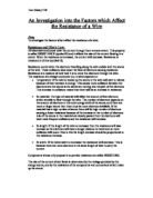
Provided there is not a significant alteration within the temperature, the results should form a graph as displayed below.
From observing the graph above, it is clear to me that the current is proportional to the potential distance. This is referred to as Ohm's Law. One very important factor that must be taken into consideration is that Ohm's Law only applies if the temperature is constant and it does not apply to all of the electrical components that we choose to use in the experiments. Ohm's Law can also be written as symbols:
V?I or V=IR
...
This is a preview of the whole essay
Provided there is not a significant alteration within the temperature, the results should form a graph as displayed below.
From observing the graph above, it is clear to me that the current is proportional to the potential distance. This is referred to as Ohm's Law. One very important factor that must be taken into consideration is that Ohm's Law only applies if the temperature is constant and it does not apply to all of the electrical components that we choose to use in the experiments. Ohm's Law can also be written as symbols:
V?I or V=IR
Where R=resistance of the resistor.
Resistivity, also known as the Greek letter Rho, ?, is the same as a wire multiplied by its cross sectional area and divided by its length. I have shown this theory in an equation:
? = R x A or Resistivity = Resistance x cross-sectional area
L Length of wire
The value of resistivity mainly depends on the temperature of the materials we use; the average temperature during my experiments was measured at 20oC. It is generally found that the total amount of resistivity noticeably increases among metallic conductors. This varies from semiconductors, examples of which are carbon and silicon, this is because the resistivity generally decreases with an increase of heat.
It is also found that the least conductive of metals generally have a high density, thus making it more probable for the electrons to collide, which in turn causes the resistance. Metals are able to conduct electricity at all possible temperatures but it is generally found that metals conduct best at lower temperatures, this is because they are low in density at this stage so the electrons can pass easily through it. Another important factor that must also be taken into consideration is that the number of conductive electrons alone does not assure us of conductivity because it also depends upon electron's mobility as well.
An applied voltage causes the electrons of the metals to accelerate and contribute to the total electrical current. The electrons can disperse and some may be lost due to imperfections in the arrangement of the atoms of the material we use, and the rate of dispersion also determines the mobility of the electrons.
The materials (wires) that I am using in my investigation are:
Nichrome; it is silvery-white in colour, tough, harder than iron and it is a combination of 80% Nickel and 20% Chromium.
The most effective use of this material was made by William T. Price who, whilst inventing the diesel engine found that Nichrome wires could be easily heated, when an electric current passed through it. From research that I have conducted into this matter I have found that Nichrome should give results similar to 108 x 10-8
Copper; it is a vibrant orangey-brown in colour. It is widely used in a variety of appliances and applications due to its excellence conducting heat, electricity, and its resistance to corrosion, its malleability and ductility and not to mention its beauty. (Copper does tend to have a beautiful colour, very warm and yet it has the shiny factor in it and is also fashionable as well!)
The principal uses are mainly electrical because copper has an extremely high conductivity rate, which is second only to that of silver. Since copper is very ductile, it can be manufactured into wires of any diameter from about 0.025mm upwards. The tensile strength of drawn copper is about 4200-kg/sq cm, it can be used in outdoor power lines, cables, house wiring, lamp cords and electrical machinery examples of which are generators, motors, controllers, signalling devices, electromagnets and communications equipment.
From previous measurements of resistivity it appears that the results will approximately be along the lines of 0.2 x 10⁻⁸
Constantan; the final metal that I shall be using contains approximately 80% of nickel and 20% copper, widely known as constantan. Constantan has a very high electrical resistance, which remains almost constant over a wide temperature range. From the research I have conducted it seems that this material should give resistivity results approximately along the lines of
50 x 10-8
Predictions
After viewing the information obtained through my Secondary Info I am now able to make a valid prediction of what the outcome of my investigation will be.
How length will affect the resistance of wire
I believe that as the length of the wire increases so will the resistance, or in other words - 'the length of wire is directly proportional to its resistance'. This is because as the electrons flow through the wire they move at a rapid rate. Because the electrons have a lot of energy they tend to collide, and therefore loose energy in the form of heat. This in turn means that the resistance of the wire has increased. A wire of longer length is more likely to have a higher resistance because the electrons will collide more often.
How cross sectional area will affect the resistance of a wire
I consider a wire whose cross sectional area is smaller would have a higher resistance. This then means that the 'cross sectional area of a wire is inversely proportional to its resistance'. I have come about this theory by the fact that a wire which has a greater cross sectional area would allow the electrons to flow more freely, thus decreasing the resistance. A wire whose cross sectional area is smaller would not allow the electrons to flow as easily because there is less room for them to move about, thus decreasing the current flow which means that the resistance has increased. A factor that would also increase the resistance of a wire, whose cross sectional area was smaller, would be that because the electrons have less to move about in they would also have a higher possibility of colliding.
How temperature affects the resistance of a wire
The higher the temperature of a wire the more likely it is to have a higher resistance. This means that the 'temperature of a wire is directly proportional to its resistance'. This is because as temperature increases the energy within the electrons also increase. This then means that the electrons move about more often which causes them to collide more often, thus resulting in a loss of energy in the form of heat. This then means that resistance has decreased.
Overall I believe that copper will conduct electricity the best, this is because it is known to be the best conductor of electricity, after silver. Constantan is likely to conduct electricity second best because overall it contains 55% copper. This then leaves Nichrome as the poorest conductor out of the three. I also predict that a wire whose diameter is greater and whose length is shorter will cause the least resistance.
Apparatus
To conduct the investigation I will have to use the following apparatus:
Ammeter
Voltmeter
Micrometer measurer
Metre Ruler
3 Constantan wires of variable diameters
3 Copper wires of variable diameters
3 Nichrome wires of variable diameters
Power Pack
Connector Wires
Crocodile Clips
The following is the circuit diagram. Its shows how the apparatus will be set up in order for me to conduct the experiment.
Method
To begin conducting the experiment I will have to set up the apparatus.
Many factors should be taken into consideration if we are to achieve fairly accurate results and also to make it a fair test. Below I have shown the steps I have taken to achieve my final results.
First, I collected the required apparatus and constructed it into a circuit, as displayed in the illustration on the previous page. I made sure that the ammeter was parallel to the circuit so that the rate the electrons travelled at could be recorded (the current). I then chose 3 metal wires of different materials, I then ensured that I had grouped the wires into 3 different SWG's within each metal, giving me a total of 9 different wires, 3 of each material and 3 of each SWG. To make it a fair test, I checked the diameter of each of the wires twice before starting any experimentation on it. Whilst doing this, I also made sure that the starting length of each wire for each experiment was precisely 1m. once the wires were all measured up I connected them into my circuit, ensuring that the voltage stayed at 4v throughout all the tests on all of the 9 wires.
Starting with 1m, I noted down all the readings that came up on both the ammeter and the voltmeter. Once I had these readings I could then go on to reduce the length of wire by 10cm through each experiment, on each wire. This process continued until the total length of the wire was reduced to 10cm before I replaced it with another wire from the remaining 8.
Results
After following the procedure as explained above, I was able to produce the following tables and graphs for each of the 9 wires I used.
Note: 'E' is equivalent to 'x 10 to the power of...'
E.g. 5.12E-07 = 5.12 x 10⁻⁷
Please look overleaf for my results...
Conclusion
After close examination of the results it becomes apparent that there were a few flaws noticeable within my predictions.
My first prediction, the longer the wire the greater the resistance, is clearly true as displayed in my results above.
My prediction proved correct since the current encounters an increasing amount of interference when the wire is longer resulting in a lower output of electricity once the current leaves a longer wire. As the wire is shortened, there is less interference resulting in a higher rate of electricity.
Although there may not be significant changes between the first and last values of resistance as with the copper results, the graphs produced interpret that the resistance is constantly on a rise. A pattern, which has come to my attention, is that the resistance falls by the same amount every time it is reduced regardless of wire material.
For instance, on the various Nichrome wires, the resistance values generally increase by 1.5? every 10cm that it is decreased.
Although copper was the most difficult wire to measure regarding resistance since the values are considerably low, it seems throughout the investigation it generally increased 0.02?
Constantan also displayed changes since generally it increased by 1.2?.
My graphs also displayed a positive correlation as the length increased ensuring my prediction was correct.
My second prediction, the higher the temperature the higher the resistance, also proved correct for a variety of reasons.
As the temperature increases within the wire, the electrons become charged and begin to vibrate. This causes a slight expansion within the wire but not enough to satisfy the total flow of electrons meaning the resistance within the wire will increase. The more heat produced by the wire, the more resistance is produced. Also, the various materials affect the outcome of the resistance. For instance, copper is largely unaffected by an increase in heat since it generally differs by only 0.02? every 10cm the wire is increased.
Therefore, the temperature is directly proportional to the resistance.
My third prediction, the bigger the cross-sectional area the less the resistance also proved correct although a significant change was not noticeable.
The wire that has a wider area has more room to allow electrons to move through regardless of material. This then should make the general flow of current slower meaning a lower resistance is produced overall.
Nichrome has the most significant changes in resistance since the starting resistance for Nichrome 0.27mm is 2.9? whilst the starting resistance for Nichrome 0.37mm is 1.6?.
This clearly demonstrates that the Nichrome wire with the diameter of 0.37mm shows little resistance and is more suitable for conduction of electricity than any of the other thicknesses. The 0.37mm Nichrome wire also shows the lowest results when it measures 1 meter to assure that my prediction is correct.
The same principles apply to both copper and Constantan although the changes between the thickest and thinnest wire are not as apparent.
My fourth and final prediction was whether or not Copper is the best conductor of electricity out of the 3 metals. I came to the conclusion that copper would be the best since it is the only pure metal out of the 3, not to mention the second best conductor of electricity in the world after silver.
Judging upon my results, it seems copper proves the definitive metal since the resistance was at a fraction compared to the other metals. For instance, the resistance for Copper 0.28mm only began at 0.10? and ended at 0.32?; a difference of only 0.25? that is extremely low compared to a metal such as Nichrome 0.28mm, which has a total difference of 16.1?.
I also predicted that Constantan would be the next best conductor since it contained approximately 55% of copper, which also proved correct. Resistance within the Constantan wires remained relatively low as displayed in Constantan 0.25mm, which had a total difference of 7.8?, which is approximately half the resistance of Nichrome 0.28mm.
Copper proved the best of all conductors since the purity of the metal resulted in less interference for the conduction of electricity. Ultimately, this meant the wire always had enough space for the electrons to move through regardless of length resulting in minimal collisions of electrons consequentially not raising the temperature of the wire. Since temperature is directly proportional to resistance, the low temperature meant very little increase in resistance.
Evaluation
After contemplating about how I performed in this investigation, I discovered that there was still room available for improvement, as there always is. After all science is about perfection.
Generally I performed well in this investigation since at first I was having many difficulties trying to understand the SWG theory and all the formulae that I later learnt, and understood. Once I had got this aside and got a move on with the actual investigation, my results were accurate to a certain degree although not quite perfect.
My first idea for improving this investigation would be to measure the results of all 9 wires 3 or 4 times. This way I would be able to construct very, very accurate results by taking the average of each wire and creating close to perfect graphs. The copper wires would require the most attention this time round because the results are fairly difficult to record precisely, but I did get them to a fairly good degree of accuracy.
Alongside this I would change the difference between the results, it should be measured every 5cm instead of 10cm to make the results more accurate and this in turn would make more reliable graphs.
The greatest alteration I carry out if I were to redo this investigation would be to have the actual experiment take place within a controlled environment this is because we had no control what so ever, over the temperature in the classroom/ lab, if it were a cold day we would have one temp and a hot day we would have another temperature. So the temperatures should have been fixed for each wire to make the test fairer.
Generally I found the most difficulty when attempting to collect accurate results for the copper wires but other than that, I performed fairly consistently throughout the entire investigation. I feel, that alongside the improvements suggested above, some of which were out of my control, I would have been able to produce a far more accurate, not to mention reliable investigation.
Daljit Malli