APPARATUS.
In order to carry out this experiment I needed the following:
-
Power Pack ~ to measure voltage
-
Connecting wire ~ allowing electricity to pass through up to the testing wire and back to the power pack
-
10 pieces of wire of different lengths and equal diameter ~ this is where I will measure the resistance in ohms
-
Ammeter ~ to measure the current
-
Meter Rule ~ to measure lengths of wire
-
Crocodile clips ~ to hold the different lengths of wire
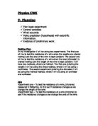
METHOD.
I set out the experiment as the following diagram shows. I kept the voltage at a constant level for all the varying lengths of wire so that the experiment can be accurate.
The voltage was set at the power pack. The current that left the different lengths of wire w was measured using the ammeter. Once both the voltage and current were recorded for the different lengths of wire it was possible to work out the resistance by using Ohms law (R=V/I).
The lengths of the wire used were increased in 5cm increments from a range of 5 to 50cm. I used the same type of wire so that the material of the wire was constant. Different materials may have different impurities that may affect the results.
The diameter of wire was also kept constant so that the rate of movement of electrons was not affected by a greater passage. The experiment was conducted at room temperature for all the different lengths so that the wire was not subjected to expansion by heat or cold.
I carried out the test three times enabling me to work out an average amount of resistance, to ensure the results are repeatable and are actual results.
DIAGRAM.
RESULTS.
The resistance is calculated by using the formula: R = V
I
Voltage was kept constant at 2 volts and the current was measured for the different lengths of wire. I obtained the following results.
Resistance was calculated, as above, by the formula: R = V (Ohms Law)
I
These were the results:
CONCLUSION.
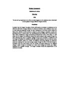
I noticed that as the length of wire was increased the resistance calculated was increased. This is represented by the graph (Fig.1). The resistance measured is almost directly proportional to the length of wire.
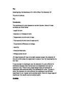
This can be seen on the second graph (Fig.2) where the graph follows almost a straight line. As I had predicted above I found that the resistance increases as the length of wire increases. This confirms my hypothesis that the number of electrons leaving a longer piece of wire is less than that through a shorter piece because as the electrons pass through the wire they lose their energy and fewer electrons actually reach the end of the wire. Electron movement is measured as current in amps.
EVALUATION.
I found that the results I obtained were a fair indication of the resistance in wires. The above experiment was carried out as accurately as the equipment allowed. The current was measured on an ammeter with a flickering needle. I would improve this by using a digital ammeter because it is a lot more accurate than an analogue because if the needle in the analogue ammeter is bent then the readings given off will be false whereas a digital ammeter does not rely on a needle or any other manual movements. This was read as accurately as I could.
I think that if I had included a voltmeter in my circuit then I would have been reassured that the voltage supplied was constant at 2 volts.
I would ensure that the quality of the wire was the same through out so that the impurities did not affect my results. This could be done by ensuring the wires for the experiment were obtained from the same manufacturing batch.
As well as making these modifications I would also improve my investigation by testing the same wire but different diameters of that wire. I would do this to expand on my investigation.
The experiment could have also been affected by other factors; for example, the wire could have been heated up during the day by the sun or any other form of heat. This would have affected the movement of the atoms within the wire.
Fig.2 shows a few anomalies. The readings of 15cm through to 30cm (15,20,25 & 30cm) and also 45cm are all above or below the line of best fit. This could be because the ammeter readings were incorrect.
In developing my investigation further, I would test how the temperature of the wire would affect the resistance measured. I would vary both the length and temperature of the wire as this would also vary the surface areas of the wire, which could affect the results.
_______________________________________________________